12 INCH TROMMEL BUILD

I'm not a great fan of the auger inside the drum simply because it's so much easier to just weld long cleats into the drum (as in your first post) they will actually provide more tumbling action.

The material will always make it's way to the exit without the spiral. But the spiral is certainly "way cool" just hard to do that's all.
In the case of a reverse helix style trommel a spiral is mandatory.

GG~
 

Last edited:
I'm not a great fan of the auger inside the drum simply because it's so much easier to just weld long cleats into the drum (as in your first post) they will actually provide more tumbling action.

The material will always make it's way to the exit without the spiral. But the spiral is certainly "way cool" just hard to do that's all.
In the case of a reverse helix style trommel a spiral is mandatory. GG~

GoodGuy I have to agree with you. I had planned to use angle iron and I have backed off of building the auger. I need to pulverize the rock and clay that we have in the soil and the best way is to have the rock and clay climb the sides and then fall back to the bottom as the material works it way to the other end. I am going back to what I was going to do in my first post. After watching a number of videos of augers the action is not what I am after.
 

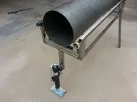
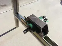
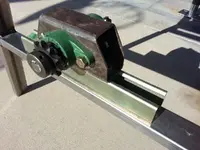
Today I was figuring out the length of the rear legs for the trommel when I had a brain fart. Typically I do not like to go to Harbor Freight to buy anything but after researching their website I saw this nice compact trailer jack. After removing the jack from the box I proceeded to extend the jack to his tallest setting. The jack appears to be well made using 1/4" hardware from the bottom plate to the mounting hardware. The plan is to use the jack to adjust the height of the discharge end of the trommel. The jack will make quick work in raising and lowering so that I get the proper angle to force the material to stay inside the trommel breaking up the clay balls before discharging.

The jack is temporary mounted until I get the lower section of the trommel frame made. The entire trommel will be 5" higher once the wheel are mounted. Currently everything is just tacked together so that if I need to make changes I can.

T18.jpg T19.jpg T20.jpg T21.jpg
 

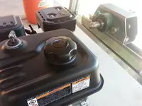
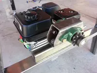
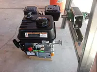
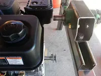
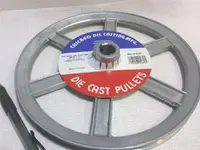
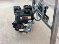
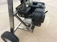
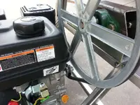
The engine mounting is proving to be a little more difficult. I am trying to balance keeping the engine somewhat centered while not having the engine sitting to low to the ground. The entire frame will be another 5" above the ground once the wheels are installed. Until I get the 12" pulley (I screwed up and forgot to order it). Also I am not using a clutch but will be using a small idler pulley to engage and disengage the belt, until I have everything on hand I will have to put the mounting of the engine on hold.

T28.jpg T29.jpg T30.jpg T31.jpg
 

Hi Mike,

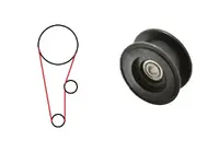
To answer your question that you emailed me I thought I would reply in the forums as others may want to know. The idler pulley removes the slack from the belt. When the idler pulley is not engaged the belt will be slightly loose until the idler pulley is engaged. This will only be used to start the engine so very little wear or slippage will take place. The pulley will be mounted in such a way that a handle will engage the pulley and locked into position to keep the pulley engaged. The 12" pulley will be mounted on the open end of the shaft seen in the photos and a belt will run from the 2" pulley to the 12" pulley with the idler pulley in the middle as in the drawing.

T32.jpg 12 inch pulley.jpg
 

How are you planning on keeping the trommel drum from walking downhill with gravity? You might think about another 2" ring on the exterior of the drum, near the discharge end with one more skate wheel on the downhill side just to keep it from walking with gravity....
 

Hi Mike,

To answer your question that you emailed me I thought I would reply in the forums as others may want to know. The idler pulley removes the slack from the belt. When the idler pulley is not engaged the belt will be slightly loose until the idler pulley is engaged. This will only be used to start the engine so very little wear or slippage will take place. The pulley will be mounted in such a way that a handle will engage the pulley and locked into position to keep the pulley engaged. The 12" pulley will be mounted on the open end of the shaft seen in the photos and a belt will run from the 2" pulley to the 12" pulley with the idler pulley in the middle as in the drawing.

<img src="http://www.treasurenet.com/forums/attachment.php?attachmentid=854923"/> <img src="http://www.treasurenet.com/forums/attachment.php?attachmentid=854924"/>

Maybe put the idler handle on a spring so that if you run into a situation where a bind happens with the drum it will force the idler loose and allow it to slip and not damage your equipment...
 

How are you planning on keeping the trommel drum from walking downhill with gravity? You might think about another 2" ring on the exterior of the drum, near the discharge end with one more skate wheel on the downhill side just to keep it from walking with gravity....

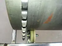
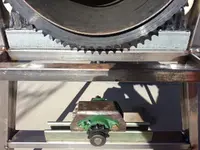
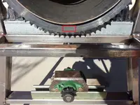
There will be a nylon bushing on either side of the sprocket. I am using the sprocket to do what others are doing by installing a second ring. Expand the photo as I have placed a red box where the bushing will ride.

T40.jpg
 

Last edited:
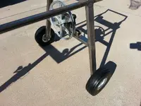
There will be a nylon bushing on either side of the sprocket. I am using the sprocket to do what others are doing by installing a second ring. Expand the photo as I have placed a red box where the bushing will ride.

<img src="http://www.treasurenet.com/forums/attachment.php?attachmentid=854942"/>

Very cool. UHMW is a very good route and you reduce the amount of replaceable bearings. You sir really have thought this through. I will be mimicking allot of this build when I do mine.
 

Thank you Doitlaynstyle... As an Engineer we over think and over build, but I wanted this trommel to be bullet proof as much as I can make it. I do not want to go into the field then have to work on it. Using Unistrut allows me to make chain, belt, and the cylinder wheels adjustments if needed using a socket wrench. I have researched spring loaded idler pulleys and most likely will use this style of belt tensioner. Just got to get the motor mounted and see what kind of room I will have. I wanted to build the trommel so that the engine was between the legs mainly keeping the engine away from where the dirt and rock being loaded into the hopper while keeping the trommel more compact. The sluice will be able to mount on either side of the trommel. I got lucky today in that I found a 12" x 3/4" bore pulley at our local hardware store. Got the pulley for next to nothing as it had been collect dust for many years. Oh and I will be using Ultra High Molecular Weight Polyethylene, was to lazy to type that in my earlier post.

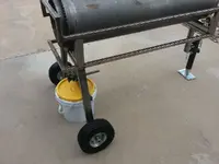
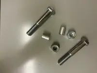
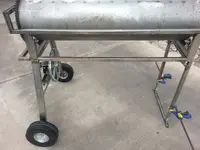
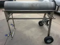
When mounting the wheels I cut spacers to fit the inside of the tubing. The spacers keep the tubing from collapsing when tightening the nut down. The wheels are 10 inch solid wheels. No tubes no flats. Wheels/Tires are very light weight.


T33.jpg T34.jpg T35.jpg T36.jpg
T37.jpg T39.jpg T41.jpgT38.jpg
T42.jpg T43.jpg

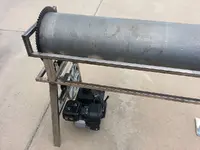
The picture angle makes the spread of the rear legs look very narrow. I measured the spread and I have a 37" spread and the upper box is 17" wide
 

Last edited:
you going to be able to move that thing around out in the bush?

looks like its getting a little heavy? nice work looks like your having have fun to, good luck.
 

you going to be able to move that thing around out in the bush?

looks like its getting a little heavy? nice work looks like your having have fun to, good luck.

Looks are deceiving. All the tubing is thin wall (.049) and have yet to pepper the cylinder with over 1400 - 1/2" holes. Once everything has been assemble for testing then will taken apart and any extra metal (Unistrut) will be cut down and only what is needed for the wheels, the bearing cradle will be left. Not that cutting the Unistrut will save much weight but it all adds up. Plus the trommel needs other items to be functional, pumps, tanks, water, etc. The cylinder will be removable if needed. I have no issues of where I will be using the trommel in regards to getting the trommel where we will be digging.
 

Last edited:
Hey Viper,

My brother and I are in the process of building a towable backhoe for feeding my 15" trommel. I'll post photos of the build on another thread. Shoveling paydirt by hand into a hungry trommel gets tiring fast. :tongue3:

We are still gathering parts and are planning to have it constructed by the end of the year. I want it to be capable of digging 10 feet deep and also have an auger attachment for test drilling up to 10 feet deep, also be capable of being towed at 70mph+ on the hwy.

Keep up the good work and I may be out your way sometime next year, we'll have to meet up and swap some ideas.

GG~

GoodGuy, We cannot use any motorized digging equipment on our club claims or on Forest Service land. A buddy of mine had his entire operation shutdown. He had claims on FS land. Had an Excavator, 3 foot diameter trommel, Drilling Rig. He ended up selling the trommel for $45,000.00. He had built the entire trommel. It was diesel / electric with hydraulics running everything. The trommel looked like Caterpillar had built it. It was a work of art.

Pick & Shovel my friend...
 

Last edited:
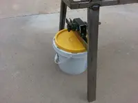
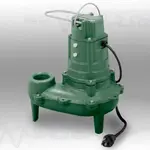
Just picked up a Zoeller pump for dirt cheap. Has an output of nearly 8000 GPH. Its all cast iron and will fit down inside one of my 15 gallon barrels once I cut the top off. Then the barrel will be submerged in a 100 gallon trough a buddy gave me.

260nonauto__51584.1372797020.1280.1280.jpg
 

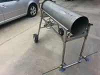
Using the jack on the discharge end of the trommel turned out to be a bust. Just did not like the functionality of the jack. So I borrowed from Jog's design of his trommel. I bought a length of 7/8" OD square tubing of which slides into the 1" thin wall tubing like a glove. Will need to make the height adjustable locking bar/pin when I get back over to the shop as I have some flat stock.

T44.jpg T45.jpg T46.jpg T47.jpg
 

I updated the photos

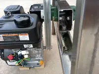
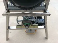
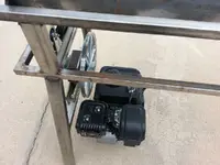
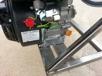
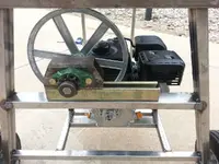
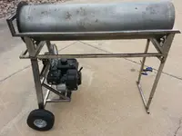
I screw around for the better part of 4 hours building a motor mount only to tear it apart and start over. I believe I came up with a mount that keeps the engine under the trommel thats strong and light. I am not a fan having the engine under the hopper. I wanted to keep the trommel as compacted as I can. The first 33" of the trommel are reserved for tumbling, washing rocks, and busting up the clay balls. The classification area will be 12 inches, no need to be full length as others have built. As you can see I made an adjustment to the big pulley. The Unistrut has already been at work allowing me to make fine adjustments. I moved the entire assemble to one side allowing me to center the motor.

I am going to build a spring loaded chain tensioner that I can engage and disengage. This will allow for slippage in the event a rock gets caught up of which in this design I do not believe it will happen due to the angle iron I will be using and the slow rotation of the trommel.

A major storm had rolled in and I shutdown on welding for the day but here are some photos. Everything needs to be welded and finished ground. Once all the welding is completed I am going to start on drilling the holes in the cylinder. Also I need to come up with a hopper design, cut the backflow ring, make a discharge chute, and the sluice.

T49.jpg T50.jpg T51.jpg T52.jpg

T53.jpg T54.jpg
 

Last edited:
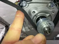
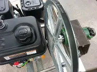
I measured for the V belt today and purchased a 4L-440 belt. Turns out to be the perfect size. The belt is just tight enough that it will not come off while the engine is idling and loose enough that I can pull start the engine without rotating the cylinder. In the first photo I am pushing on the V belt where the spring loaded belt tensioner will be located. To start the engine the tensioner will be disengaged to allow the engine to warm up then the tensioner will be engaged to get the cylinder to rotate. A simple solution in not using a clutch or the more expensive Honda engine. I have left room if I need to use a 14" or larger pulley to slow the cylinder under 15 RPM's.

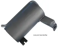
On another note you will see that I have moved the pulley and sprocket on the 3/4" shaft as close to the flange bearings as I can. The reason for this is to remove stress on the bearings and shaft. This holds true for the pulley on the motor as well, you want the pulley to be as close to the bearings as possible. I am using a Predator engine of which is a knockoff of the Honda. From the reviews in the Go Kart forums the engines are worthy of being used. They are even making mods to the engines to raise the RPM's without floating the valves, not that I need to mod my engine. My plan is to run the engine at the lowest RPM I can, but until I fire the motor up I have no clue. One thing I may do is build an exhaust manifold and use a larger muffler from a gas power golf cart to bring the sound level down.

T56.jpg T55.jpg T57.jpg T58.jpg
 

Last edited:

Top Member Reactions

Users who are viewing this thread

Back
Top