12 INCH TROMMEL BUILD

MDVGA posted this in the sluicing forum. Thought the ends were rather clever idea. It also shows a slow rotational speed.

So instead of welding a band or 16" bike tire to the outside to use a serpentine belt, use a trailer tire or donut spare from a junk yard

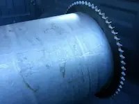
As much as I wanted to use a serpentine belt the added RPM's were to great due to using the 12" cylinder as a pulley so its back to the 14.69" sprocket. I called a buddy of mine who put me in touch with a local machine shop. Turns out this shop can handle up to 36" on their lathe. This shop is going to open the sprocket up so it fits the 12" cylinder tight. Cost $35.00. To me that's well worth the cost. I would have spent more money in blades, grinding wheels, and time in getting the sprocket to be dead center with a dial indicator. Now its slide the sprocket onto the cylinder and TIG weld the smallest welds you can imagine. The plan is to use the solid surface on the sides of the sprocket to have the nylon bushing make contact to keep the cylinder in place. This will eliminate having another 12" ring cut. I may be wrong with this idea but I am going to explore it first.
 

MDVGA posted this in the sluicing forum.

I don't understand the design. The sluice is just below the hopper. Does not seem like the dirt and rocks would get much of a chance to get washed before traveling down the trommel considering the paydirt recovery is dropping out at the beginning and not at the end. Then there is the channel like sluice that is only catching water and maybe losing paydirt. With a screen the entire length of the cylinder and very few holes for pay dirt to drop out of the outer shell I would bet that gold is being lost.
 

Last edited:
I don't understand the design. The sluice is just below the hopper. Does not seem like the dirt and rocks would get much of a chance to get washed before traveling down the trommel considering the paydirt recovery is dropping out at the beginning and not at the end. Then there is the channel like sluice that is only catching water and maybe losing paydirt. With a screen the entire length of the cylinder and very few holes for pay dirt to drop out of the outer shell I would bet that gold is being lost.
They shouldn't have screen at the front part, and may figure that out.

The material is supposed to drop through the screen further down and then the reverse helix action can take place. As it is they may simply plug their forward holes where the concentrate is supposed to come out after being washed all the way up the drum.

It says at the beginning that the aft chute doesn't have the ripples in it yet.

It seems most of the water coming out the back is wash water. They don't need spray after that aft sluice.
 

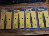
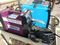
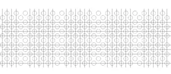
My attack on drilling some 1400 holes will begin soon. I have made up a number of drilling guides to get the holes all in the correct position. Will drill pilot holes first followed buy the Unibit that will size the holes to 1/2". My welding cart with my Thermal Arc TIG welder and Miller Millermatic 211 MIG welder. Other tools I will be using will be Chopsaw, Grinder, Plasma Cutter, SawSaw, Hand Drills, Drill Press, etc. The 14.69" sprocket should be here this week and then its off to the machinist to have opened up to a 12" bore. I already have most of the 1" square tubing rough sized to the lengths I need. Pre-cutting to within 1" makes it much easier than handling a 20 foot piece of tubing in the shop.

xtqr.jpgs0a7.jpg
 

Last edited:
Az, Great start to your Build! If I may make a suggestion. The angles running the length of the cylinder, Seal weld them and cap them. They will fill with material (and possibly your gold) if you stitch weld them. And be careful of warping the cylinder. You can weld a couple of inches at a time in steps around all of the angles at once to minimize the heat and warpage.
 

My attack on drilling some 1000 holes will begin soon. I have made up a number of drilling guides to get the holes all in the correct position. Will drill pilot holes first followed but the Unibit that will size the holes to 1/2". My welding cart with my Thermal Arc TIG welder and Miller Millermatic 211 MIG welder. Other tools I will be using will be Chopsaw, Grinder, Plasma Cutter, SawSaw, Hand Drills, Drill Press, etc.
You're not going to use the plasma to make the holes? I'd make a template of maybe 2 rows of the hole pattern and go to town.

I'd also make a simple turn table to burn the gear.

But I don't have a plasma,.. sniff, sniff,...
 

You're not going to use the plasma to make the holes? I'd make a template of maybe 2 rows of the hole pattern and go to town.

I'd also make a simple turn table to burn the gear.

But I don't have a plasma,.. sniff, sniff,...

You should have clicked on the third photo of my first post. The drill guide is posted, but here it is again.

5dls.png
 

Az, Great start to your Build! If I may make a suggestion. The angles running the length of the cylinder, Seal weld them and cap them. They will fill with material (and possibly your gold) if you stitch weld them. And be careful of warping the cylinder. You can weld a couple of inches at a time in steps around all of the angles at once to minimize the heat and warpage.

Yep I know all about burning here and there to control warping. Thanks on the tip about closing off the ends. I still may do a spiral to help control movement of the material.
 

I picked up my sprocket today and what a tight fit on the cylinder. I could only tap it down about 1/2" due to the spot welds on the seam needs to be ground down, but the machine shop did and amazing job. It fits so tight I am only going to TIG weld four 1 inch beads on both sides. I am also going to use the sprocket with nylon bushing on either side to keep the sprocket from walking instead of a separate ring that others have used.

g0jx.jpg qrng.jpg
 

Last edited:
Not sure where the 14.69" sprocket is measured from. Whether its the overall diameter or from the saddle of the teeth of the sprocket. Until it arrives I will not know. If its the overall diameter then I have 14.69" minus 12" = 2.69" divided by 2 = 1.345" that will be raised above the cylinder. Parts are slowly trickling in. I need to pick up a fresh bottle of 75/25 mix of gas for my TIG and MIG welders. The flange bearings and sealed bearings for the wheels will be here this week. I made up the flange bearing cradle from 2" x 3" tubing I had in the shop. Once the bearing are here I will be able to drill and get them aligned and mounted. The plan is to make the cradle adjustable so that I can make fine adjustments to the chain tension. Although this will also make a change to the 12" pulley. I believe I will make the motor mount adjustable so that I can make tension adjustments on the pulleys/belt.

View attachment 829732

Right now my time is really limited to work on the trommel as I have to squeeze in building poker tables along with my regular job and prospecting for gold.

Table blanks I just finished up and custom table I just delivered.

View attachment 829735 View attachment 829733 View attachment 829734

Viper, NICE poker table! If you ever have a client looking for a table made with something unique get a hold of me with a PM. I've got wood that will knock their socks off.
RP
 

Viper, NICE poker table! If you ever have a client looking for a table made with something unique get a hold of me with a PM. I've got wood that will knock their socks off.
RP

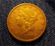
I see that you are in MO. I was born in Cape Girardeau, MO. Use to go back ever summer and was to go back this summer but the old house burnt to the ground prior to our departure. We were to collect the old hardwoods from the old 17 bedroom Mansion and surrounding buildings. This 1877 twenty dollar gold piece came from the old house. I had planned to MD the entire area as my mother told me that old coins were buried on the property.

image22fv.jpg
 

Here is the cradle with bearings attached. I used four separate bolts to mount the bearings. Using two bolts passing through the tubing you risk collapsing the rectangle tubing unless spacers are used on the inside of the tubing against the walls of the tubing. I have decided to use Unistrut to bolt the cradle to the Unistrut, this will allow for slight chain tension adjustments by sliding the cradle away from the center of the cylinder to tighten the chain tension. I will use Unistrut as motor mounts also this allowing me to slide the motor to make tension adjustments to the belt/ pulleys. Granted the shaft is longer than I need and will cut so that the sprocket and pulley are as close to the bearings as possible so there is less stress on the shaft.

View attachment 831631 View attachment 831632 View attachment 831633 View attachment 831634


Hey brotha,
After finally getting to look at this pic on my computer instead of my phone I noticed that your bolts here are a 1/4 inch too short. We use nylocks all day long out here because we build locomotives and we dont want them rattling apart. In my experience if you don't have at least 2 threads penetrating past the nylon ring on the nut then it can come loose. not saying it would but it could. Your build Is looking AWESOME and I will be mimicking a good portion of it this winter. Thank you so much for your posts! Keep em coming.

Those are temporary bolts until final assembly when everything is painted Desert Sand, then the correct bolt length will be used. Thanks for checking in. More photos will be posted. Just ran a calculation on my drill layout of drilling all the holes in the cylinder and I have about 1400 holes to drill. Going to cut up some MDF on the table saw and build a jig to clamp the framework while welding so everything stays flat and square. Years ago I use to have really flat welding jig tables I built when I use to build gym equipment.
 

Last edited:
1350 holes to drill.


:censored: that! LOL thats a bunch o holes. Go down to home depot and get a laborer haha. Good call on building a jig first. Always a good plan even if it takes longer.
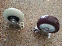
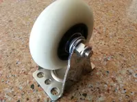
 

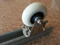
I decided that the larger caster wheels were not going to work. It’s back to the rollerblade wheels. I picked up some bearing that were new from a local used equipment sport’s shop that the sales person had no clue what they were worth. I got 8 bearings for $3.00, but the bearings typically sale for $10.00 per bearing. Next I went to Harbor Freight and bought some cheap casters only to salvage the mounting bracket of which was the plan. Drill two 1/4" holes . This will allow me to lower the cylinder as low as possible on the Unistrut.

3k7i.jpg 4tfx.jpg yi1q.jpg
 

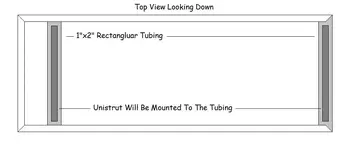
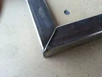
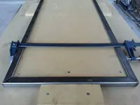
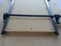
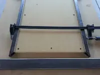
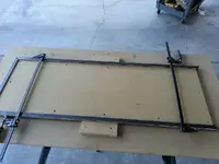
Got a late start on the base frame of the trommel today. I made a jig (MDF) to keep the frame square and flat while welding. In the drawing you will see I am using 1”x2” rectangular tubing. The tubing will be the mounting support for the Unistrut that the wheels will mount to and allow for fine adjustment so the wheels touch the cylinder evenly. Most of the frame will be built from 1"x1" square tubing. My time is limited and this build is going to drag on, but if I can get one free day to work on the trommel it will come together quickly as I have all the parts to complete the trommel. The 1"x2" that welds to the end will require removing the frame from the jig to fit and weld in place. Prior to removing the frame from the jig I will tack weld a brace to hold the frame square.

I hope I am not boring anyone with this step by step build. The plan is to help motivate others to build their gold processing equipment. With all the clay we have in Arizona this trommel will help break up the clay prior to heading down the sluice.

3cgj.jpg sn8t.jpg 68ex.jpg hwpa.jpg uhhc.jpg o1s9.jpg
 

Last edited:
I hope I am not boring anyone with this step by step build.
I was going to comment earlier, it would be awesome if you could actually show more especially with the welding. I don't recall anyone showing welding steps like you're doing with the frame. That can be quite the b**ch as the heat distorts the metal and you find the next piece doesn't fit or it's simply not square.
 

I was going to comment earlier, it would be awesome if you could actually show more especially with the welding. I don't recall anyone showing welding steps like you're doing with the frame. That can be quite the b**ch as the heat distorts the metal and you find the next piece doesn't fit or it's simply not square.

Not my ideal welding table (MDF) but it will work. Use to have a shop that I had tables designed for clamping metal down to weld but I do not weld much anymore to warrant having that setup anymore.

The key to controlling distortion of metal is to weld in small increments and allowing the metal to cool down before continuing. In the case of this bottom frame I will tack weld it all together and tack weld a temporary brace across the open end. Next I will weld the corners followed by a cool down period, remove the frame from the jig and weld the underside followed by another cool down period then weld the ends of the corners and the inside of the corners.

Will be Mig welding with 75/25 mix of Argon/CO2 and .023 solid wire. AMPS somewhere between 55 and 70 to get deep penetration, wire speed about 30 on the Millermatic 211 welder.
 

Last edited:

Top Member Reactions

Users who are viewing this thread

Latest Discussions

Back
Top