pulse valve mineral jig build... need valve seat design help

We had a saying in the concrete business...."a broom finish can cover a lot of sin". Haha, made me laugh.. You must be old school like me Jim.

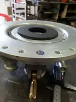
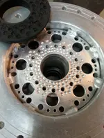
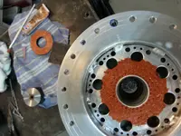
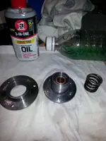
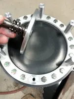
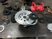
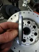
Pulse valve update,. I am still waiting on gasket material delivery. But i managed to get a start on the new valve seat. I made a few flat seals from different recycled rubber parts, and settled on the one on top of the valve body. It is 1/2 inch thick solid rubber ( shore A65? ), made from a anti vibration mount ( top left ). I machined a bottom step on it for mounting. The aluminum ring, also has a matching inverse step , that will be the seal lock ring.. I have yet to drill and tap for lock ring fastening.. Also on my list, drill a few more water supply ports in the defuser plate , as the new seal assembly will restrict water flow.. ... FYI,:The recycled suction cup rubber (on right) is interesting. It is 1/4 inch thick rubber , with a metal plate center ( 3/32" ). Keep that in mind for specialty repair and build projects. You can never have too many spare parts kickin around.. Lol.. Ken
20160516_212257.jpg20160516_171944.jpg20160516_172035.jpg
 

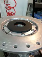
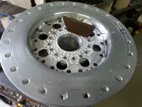
Here is another build update,,, i textured the bottom surface of the rubber seal with a forstner bit 1/4", and dimpled the aluminum defuser plate with a 3/16" drill bit. This creates a bonding surface area with better holding abilities. I used ultra copper silicone (high temp) to glue the seal ring to the plate., let it set up for 24 hours, then installed the lock ring.

20160517_214716(0).jpg20160517_221214.jpg20160518_233739.jpg
 

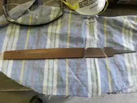
Procedures and custom tools.. The steel parts were soaked in rust inhibitor, then coated with 3 in one oil for rust proofing.. Made a custom file, to file raised burrs around the centering displacement pipe.. I used a thin cut grinding disk to cut the file, then lightly ground the sharp edges.

20160519_203941.jpg20160517_184821.jpg20160517_184852.jpg
 

Yes !!! The Gasket material finally arrived. :laughing7: .Update on ..Template.. Customized Hole punch.. Valve stem Disk.. .........................................................
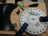
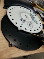
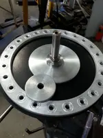
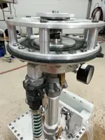
The Hard board template, has an index tab as well a dimple to recognize the top for ease of placement . The hammer type hole punch (has green tape on it ) was machined on the cutting end to fit the template hole size and depth. The new valve stem disk (3 1/4 ") is twice the width of the first one . Well , i should have an operational update later on today..... Keep your fingers crossed.. Lol.. Ken

20160520_191613.jpg20160520_191914.jpg20160520_200444.jpg
 

Looks good, Ken....looking forward to a video of it running.
Jim
 

Jim and Russau...Well i would like to see a video of it running too !!!, and i would like it a lot more if it worked!!!.. Haha

Same results as before.. Not pulsing, The diaphragm gasket is an improvement as is the wider disk. I tried using the gas water pump and 1 inch hose, same results, just more water volume leaking by... I tried 3 different size disks , and a rubber "O" ring under the disk to reduce the seal contact area.. That increased the pressure to 20 lbs on the gauge , same results as before... Leak by, no pulse at all...

20160520_215544.jpg20160520_220443.jpg20160521_145416.jpg

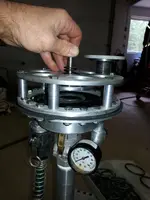
(second picture), i took off the top control plate and valve, you can see the rubber seal is dimpled in the center. It is holding the water capacity in the stand pipe , by suction . (so to speak).. Well,, back to the drawing board.. Lol... ANY input ?, thoughts, ideas, off the wall ideas, reply's, info, pics, drawings, stories, brain wave, light bulb moment, criticizim, jokes, like:> ( Hey !!, maybe use the pulse valve for a door stop. Haha. )... Would be welcome.. Thanks,.. Ken
 

Well since its a water pulsed device ,why not pulse the input water to this device ? possibly a enclosed Pelton wheel that has a flat spot on its outter edge (this is the pulsed action)and 2 inputs and 2 outputs for the pulsed action you need. 1 input / output wont keep it running) This device dosent need to be a big device because it only controls the device you made. The device you made handles the full force of the water that needs to do the work. I made several of these with another group and they don't want it developed into any commercial type of device , so I wont post a picture of it. and from what I did post , you could come up with somesort of device that should ease your problem. GOODLUCK!
 

Correct me if Im wrong But isn't the pulse valve suppose to work like a ram pump? I see 3 things here all constant water psi, spring psi and vac. the vac needs to be broken at some point and the diaphragm needs some travel before the spring loads up. If you where to add a check valve circuit to the stand pipe to break vac it should help the spring lift and load. is the spring you are using a valve spring from a auto or small engine? what about a tapered spring the spring will load differently. or move the Pulse valve from the top like you have to the side and lower in the hutch this will help with the vac also.

just my 0.02 cents worth


Bill
 

Last edited:
I would try a MUCH lighter spring.
Jim
 

russau, . Bill-saf,. Jim, . Thanks for the reply's, Gives me a lot to think about. and helps a lot..

My goal from the start was to build a very small, light weight, compact jig, completely powered by a 1 "gas water pump. For testing remote areas. I have no experience with jigs,( as you can prob tell) only what i have seen on forums etc.. I expected it to work ,also expected it to be too weak to fluidize the material .

-To- Pulse- the water supply line is most likely the way to go, as this would help deliver more energy, Needed to lift all the material.
-I have seen a rotary water valve ( on, pause, on, pause, etc) that was powered by electric dc motor , belt and pulleys. rheostat control for fine rpm tuning.
-I will think hard and long about the 2 input, 2 output ,wheel flat spot thingy. very interesting. .
-Similar to a ram pump, but they discharge a lot of water to collect energy, trip valve activates, sends a small volume of water to storage.
-Yes, the constant water supply is a problem, spring psi doesn't really matter with constant water pressure as i will show in next post, with pics
-There is no vac when the supply water is on .( as in last test.) When it is working properly there will be a momentary vac.(so to speak) holding the water column in the stand pipe. The second pic in the previous post was to show the seal was working well.
-The spring is from a early 80s honda bike engine 80cc, exhaust valve spring
-i have tried a few more springs, heaver, lighter, cone shaped, and no spring. Lol .-
I tried no spring , just my hand, pushing, pulling etc. I can not close the valve with most of my weight on the valve stem top. So i did a valve stem lifting force test..Will post a picture of that redneck testing setup. Lol

Thanks again for the posts. ... Ken
 

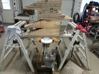
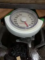
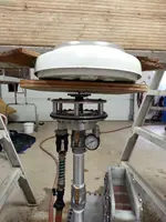
Valve stem lift test. ... It Seems like the constant water supply is problematic and the power of the diaphragm overpowers the spring. .So, i set up two 4 foot steps with a horizontal plank clamped to the rungs. I then placed wood blocking on the plank. About 120 lbs combined weight.
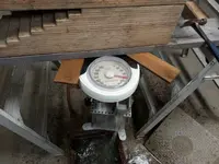
The jig was placed under the bridge(so to speak) a small steel plate on the valve stem top, a small plywood square, then a weight scale. Finally wedged cedar shims to fill the remaining gap on top of the scale to bottom of the plank..
My starting point on the scale showed 20 lbs. Then progressively increased the weight by hammering in the shims to add weight to the stem.
At 45lbs when i turned on the water supply the scale went to 65 lbs, and a very loud vibration pulse occurred,(fast like a machine gun). The water in the screen box was spiking up maybe 1.1/4 to 1.1/2 inch , looked liked upside down icicles. Lol So , i left it running, and added 4 ilbs of steel shot. The ragging was fluidized a bit for sure. There was no wave action, just the usual steady stream on the discharge.
I continued testing up to 115 lbs on the scale, turned the water supply on, scale went to 120 lbs. When you turn the water on you can see the valve lift the scale. a lot of force there for sure..
The valve body pressure gauge was mostly at 10 to 15 psi. during all tests., even at the 120 lb lift.
20160522_103430.jpg20160522_101809.jpg20160522_125122.jpg
 

20160522_125310.jpg20160522_103325.jpg i did not get a pic of the high water spike event,
 

Ken, you can calculate all this stuff, as a check. Sounds like it tried to work if you had spikes in the water. I doubt you'll see a jigging action with this type of pulsation....more like the water is slightly moving. To determine the pressure on the spring, just calculate the square inches of surface area on the bottom of the diaphragm, and multiply by the incoming water pressure. If you had a 6" diaphragm, with a 1 1/2" outflow pipe, you'd have roughly 26.5 sq inches of surface area acted on by the water pressure. At 20psi that would be 530 lbs of lifting power. So, if the spring required 200 lbs to compress it 1/4", the valve would open when the water pressure hit 7.5 psi. That would seem to be a very fast rate of pulsation, to me. As the spring rate goes up, it would require more and more pressure to open the valve, which would take longer to build up, so the pulse rate would slow down. That makes me think the spring rate is too light, but that doesn't take into consideration the rate of flow from the input. As that rate increases, the pulse rate would also increase. Obviously, there are a whole bunch of variables in those pulse valves, including: spring rate, diaphragm diameter, outflow diameter, and input water pressure and flow rate, not to mention the size of the ragging box.
I'm wondering how an adjustable valve on the input line would effect the pulse rate? Slowing the input flow should slow the pulse rate, as it would take longer to refill the chamber after each pulse-valve opening.
Jim
 

Last edited:
Thanks for the calculations Jim..
Wow,Thats a lot of lifting force, i guess similar principals as hydraulic cylinder or bottle jack.
The outflow and stand pipe is 1, 1/4 ".. Your right,There was no jig action, but i had to let it run like that for a while as a glimmer of hope. Haha ..The total valve width is 7.5/8", the inside exposed rubber width is 6.1/16". Yes, the variables list is long. I will try choking the supply valve and other ideas for sure.. May be a while to update the results..

I was watching some of your YouTube videos, last one was (Round Dry Jig at the Big Lost) another cool build!!! I never see any tire tracks in the river bed. Do you use a wheeled cart or dolly, or carry it all in , arm strong method ? and a full size car battery ? You are only a few years older than me, not sure how far i could go with that battery. Lol.......Ken
 

Last edited:
LOL....a lifetime of concrete work will toughen you up....................................or kill you. I don't have wheels on any of my prospecting gear. But, there have been times I wish I did.
On that last post...I was just writing as things occurred to me as I thought about your setup.....sort of noodling. It should be pretty simple, but it's not turning out that way. I may end up building one to figure it out....LOL
Jim
 

Spudnik, First off, the machine work is beautiful..

I've watched your video, and read the thread... And thought about it... Unless I'm missing something, I don't think this is going to work the way you have it...

The way I see it.. The rubber is a bladder that as it expands creates pressure... The spring holds a valve closed and is supposed to pop off when a certain pressure
is reached... Is that the idea????

If that is how its supposed to work.. Your spring is coming from the wrong direction.. Backflow valve, or a check valve is what I think you are trying to replicate.. Difference here
is you are looking for a higher blowoff pressure so that it opens and closes and pulses... Where as in a "normal" application you would just want it to stay open when there is flow.


https://www.google.com/search?tbm=isch&tbs=rimg%3ACVKF_12f7EbYMIjgZVCoeT_1UVz31tRN9Ko4zrBXLkfBHM7pO_1OeWW8Jir77YiQBE0MbReaWPCs-aPTd8OmTmjDsIwzyoSCRlUKh5P9RXPESFjSh8HV_1a9KhIJfW1E30qjjOsRMUYKh3Hc2NgqEgkFcuR8EczukxFa4An2I6ximyoSCb855ZbwmKvvEfpAHU1vbhAnKhIJtiJAETQxtF4R0kbYAWuw-oIqEglpY8Kz5o9N3xEQHCegrK9YwyoSCQ6ZOaMOwjDPEcZV12g4_1Ec7&q&safe=off&bih=879&biw=1903&ved=0ahUKEwjE1Z_kq_HMAhWqpYMKHQRJAukQ9C8ICQ&dpr=1
 

I just went back and looked at this all over again...

You are trying to use the rubber bladder to lift the valve, against the spring pressure...

Even if you put a solid disk over the bladder, it would lift the valve, but as soon as a TINY bit of liquid escaped, the valve would close again..
At one point you had a high frequency pulse, and I think that is about the best you can get this way... Other than that, its going to hold the
valve open slightly and leak, which is what its doing.. LOWER spring pressure should, at least in my mind, should get you a longer pulse, but I don't
think its going to be a low enough frequency to run this thing.
 

ken,
I know how you feel right now been there. From what I see from your pics and pics from others your stand pipe from the pulse valve is going in to the top of the hutch and others come in low and on the side of the hutch. my thinking when coming in to the top of the hutch even when filed with water will have some vac and coming in low and on the side the hutch will help balance from vac to pressure like a manometer will give some type of head may not be psi. I hope you get what Im trying to say this is where I have trouble putting into words. so I found some vid's on utube for you to take a look at maybe it will help you on your quest.

Bill


Last edited:
WOW!!

That's a lot simpler than I thought...

Though, the first video has the spring pushing down on the valve (though the diaphragm is pulling up) and in the other 2 vids, the spring is actually pulling the diaphragm up,
not pushing it down onto the valve seat. Though neither spring is much of anything. It does seem there is a slightly heavier pulse with the spring pulling the valve seat away..
I'm also guessing that the head height has a lot to do with it.... I had no idea there was head height and vacuum involved.

Seeing that, and springs pushing AND pulling.. The OP is using WAY TOO MUCH SPRING... I'm thinking it would work without a spring at all, and a spring is to fine tune...
On the first one, the diaphragm is fighting the spring, its dished in (stretched) a lot, so it might not be pushing as much as it appears.

I think I might have to build one of these.
 

Top Member Reactions

Users who are viewing this thread

Back
Top