Dawn of the stealth dredge

It might sound stupid at first, using well pumps in this application. But I did do a little bit of research first. I started here, where Keene engineering put together a paper on dredging basics/troubleshooting/making your own. Its one of the few places that I was able to find actual number on the flows and PSI needed, but here is the critical distinction:

Flows and PSI needed for suction nozzles/ power jets consumption, NOT what the maximum rating of the pumps are.

http://keeneeng.com/pdfFiles/Keene Pumps 2019.pdf

According to them, here is the important part of the paper for those uninterested in following the link :P

2” dredge pump specifications.
P90G pump produces up to 100 GPM and up to 160 foot head.
2”suction nozzle works at 45 GPM at 35 psi.
2” power jet runs at 63 GPM at 30 psi

2.5” dredge pump specifications.
PHP160 pump produces up to 200 GPM and up to 160 foot head.
2.5” suction nozzle works at 78 GPM at 45 psi.
2.5” power jet works at 106 GPM at 40 psi.

3”and 4” dredge pump specifications.
P180 pump produces up to 250 GPM and up to 160 foot head.
-3”and 4” suction nozzle works at 106 GPM at 45 psi
-3” and 4” power jet runs at 180 GPM at 35 psi

Now the performance characteristics of the pumps:
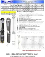
81C8TLPYApL._AC_SL1500_.jpg

Power jets/ suction nozzles, according to the keene paper, run at 45 psi. Converted to feet of head thats around 104 ft. On the performance curve for the electric pumps at 103 ft-head they should be putting out roughly 23 GPM, so for two pumps 46 gpm.

Clearly this is still low for a 3" or even a 2.5" dredge, according to the keene paper. It would be more than enough for 2" though. I just decided to incorporate them into a 3" system first and hope that the increases in efficiency outlined by Phil (Infinity jet, submerged system) would be enough to allow it to function as a slightly under powered 3". And im not sure, but it seems I might have reached that point on the first fireup, with no performance optimization.
 

Incorrect. You can not run well pumps in series. Running 2 pumps will give you 66 gallons, but the max PSI will not change. As an FYI, on pumps made to run in series, you do not double the volume. 2 pumps can be run in series to give higher pressure, or in parallel for higher volume, but not both.


The pumps on not being ran in series. One pump feeds two jets. The other pump feeds the other two jets.
 

Before worrying about the generator, I would focus on refining the system so you get a working prototype.

Basically, the goal is to produce balanced flow out of the jets so you are pushing at the center of the pipe thereby reducing losses because you are not losing energy on the sides of the tube.

To get the water moving evenly, the first thing you need to do is add an 18" of straight tubing to the output side of the jet so the column of water has time to create uniform suction. You mentioned this early when talking about the "bulged section seen at the end provides a longer length of taper, in theory giving the water more time to become co-linear with the direction of flow down the pipe." You just need to make it longer.

Next, for the system to work properly, the water has to come out of all four jets at the same pressure. If one of the jets is off, it pushes the column of water off to one side and efficiency drops dramatically.

You are currently using one pump to feed two jets, and another pump to feed the other two jets. My concern is one pump might produce slightly more pressure and screw the whole thing up. As such, I would print a 4-way adapter so all four jets are fed by one pump.

Also, it looks like you are using 2" flexible hose for your inlets. That could be part of the problem. Because you have a 3D printer, I would make one adapter that has (4) 3/4" hose outlets, another with (4) 1" outlets, and another with (4) 1 1/2" outlets. Test each of them with the corresponding size of tubing and see which works best.
 

The pumps on not being ran in series. One pump feeds two jets. The other pump feeds the other two jets.

That doesnt add PSI. You stated that running 2 would give you 180psi, which is wrong.

But spend your money however you like, build whatever you want. I'm out of this thread. I laugh every time someone comes along with ZERO experience in prospecting, mining, dredging, hydrodynamics, mechanics or electronics and thinks they are going to build a better mousetrap when they've never seen a mouse.

Peace out!


This link provides information that will help you understand how this "mousetrap" works.

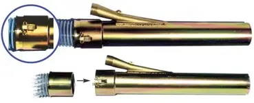
Gould Engineering Bazooka Dredge
 

Ive got a power source coming next week, and with that I will be able to take it to a local river and see how it goes through real material.

Its not a terribly quite generator unfortunately, so I might have to experiment to get it quieter if i decide to. On the other hand its small, light and quite powerful for its weight. If one can believe the specifications they put out for it.
 

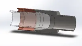
Oh, and a few people mention keep mentioning jets. This nozzle doesn't have jets; Or at least, it has only 1 jet, shooting inwards at a full 360 degrees. The 4 smaller flexible hoses are there just to get the pressurized water into the first chamber, where it equalizes around the sleeve and then shoots into the main line. I can put together a cross section of it, if that would help people visualize it?
 

Last edited:
Oh, and a few people mention keep mentioning jets. This nozzle doesn't have jets; Or at least, it has only 1 jet, shooting inwards at a full 360 degrees. The 4 smaller flexible hoses are there just to get the pressurized water into the first chamber, where it equalizes around the sleeve and then shoots into the main line. I can put together a cross section of it, if that would help people visualize it?


That would be great. From the pictures, I thought you built Gould's jet.
 

cap1.JPG
It comes in 3 parts, each a different color in the diagram. The translucent part is the sleeve, which is able to slide back and forth in order to increase or decrease the gap between the two tapered sections. Its these 2 tapered sections that form the jet, 360 degrees around the center section to accelerate water/material down the hose. The 4 smaller hoses just feed water into the cavity around the center section, allowing the water they carry to equalize within the housing and then jet down the pipe.

Does that help?
 

Untitled2_zpsb9c12566.jpg

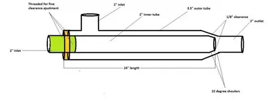
Here is a sketch of the basic concept, from elsewhere on this forum. I just reduced the need for the 24" section drawn in it, which is included in order to give the pressurized water that is injected into the outer cavity perpendicular to the ultimate direction of flow, time to turn 90 degrees and become more laminar again.

Since my water is injected into the back of the housing, its already traveling in the correct direction.
 

Last edited:
I hate to say it, especially after bickering with the naysayers, but what you built is not an Infinity Jet...........It's an inefficient power jet.

Give it a try though and let us know the results.
 

Now im confused. What is an infinity jet then? A power jet is this:
oversize_powerjet.jpg

Pressurized water injected into the main path on one or more sides. The more ports that you have the better it performs, but more complexity/fabrication. The infinity jet takes the port and spreads it all the way around, so that its injecting water in a full circle along the perimeter. I definitely haven't built a power jet here. My water is injected in all along the perimeter of the main path, at a sharp 11 degrees.
 

Last edited:
Now im confused. What is an infinity jet then? A power jet is this:
View attachment 1852510

Pressurized water injected into the main path on one or more sides. The more ports that you have the better it performs, but more complexity/fabrication. The infinity jet takes the port and spreads it all the way around, so that its injecting water in a full circle along the perimeter. I definitely haven't built a power jet here. My water is injected in all along the perimeter of the main path, at a sharp 11 degrees.


Calling it a "power jet" was a poor choice of words on my part. The point I was trying to make is, power jets are simple but very inefficient so you have to throw a lot of water and pressure at it. Your design will work too........But you are going to need a LOT more volume and pressure (Any design, no matter how inefficient, will work if you throw a lot of water and pressure at it).

Plainly stated, when you tried to fix what you perceived as inefficiencies with the design of the Infinity Jet (By making it shorter and injecting water into the back of the housing), you removed the two design components that make the Infinity Jet work. And please understand I am not trying to insult or discourage innovation. Many people have tried to make a more efficient dredge for decades (Myself included), and there are plenty of naysayers out there (like those above) that will say you are wasting your time, "reinventing the wheel" etc etc etc Ignore them.

You should call have called your post THE DAWN OF THE 3-D PRINTER because resins that withstand high pressure have only been on the market for a few years. As such, somebody is going to take past ideas that could not be turned into reality due to manufacturing limitations or cost, and revolutionize the industry by printing the parts needed to make a very efficient dredge.

My two cents............Start over from scratch by printing an Infinity Jet without making any changes to the design, and get it to work using the smallest pump possible...............Then begin making changes to find the most efficient setup.
 

3”and 4” dredge pump specifications.
P180 pump produces up to 250 GPM and up to 160 foot head.
-3”and 4” suction nozzle works at 106 GPM at 45 psi
-3” and 4” power jet runs at 180 GPM at 35 psi .

These numbers might be Keene but it's a misprint if it is... The P180 runs at about 350gpm and a 3" dredge will run almost perfectly on 225gpm but not much less. A lot of the smaller Keene dredges are severely underpowered for production. The last line in the quote above should read 300gpm, not 180. The suction nozzle numbers are ridiculously low because a 400gpm pump is needed to run a 4" suction nozzle with their 16" wide box system. Their P180 will put out just enough water to almost run a 4" suction nozzle... but it's still not enough to run their 16" wide box the way it was designed.
Aside from that, your looking for numbers for a 3", so figure 200-225gpm to be happy unless you're going to reduce down to a 12" wide Keene style box, where a 150gpm should be fine.
 

View attachment 1852501

Here is a sketch of the basic concept, from elsewhere on this forum. I just reduced the need for the 24" section drawn in it, which is included in order to give the pressurized water that is injected into the outer cavity perpendicular to the ultimate direction of flow, time to turn 90 degrees and become more laminar again.

Since my water is injected into the back of the housing, its already traveling in the correct direction.

You don't need 24" because you will just be creating more pressure loss, the infinity jets work great as they were designed, so cut yours in half at least for a 3". The water only has the one way out and it will create more pressure - the shorter you can keep it.
Reggie Gould was a really smart inventor, we spent many hours together back in the day discussing his dredge and our other designs that our group of friends were using every afternoon at Pioneer Mining. There was a group of us that got together at least 3 times a week, he gave me one of his dredges to try and it worked great back in the day when his parts were all welded together. We discussed everything from 2" to 12" dredges and how to best customize them. It was lots of fun and I do miss those days with our drawn out discussions on gold mining of all types. I built my first dredge back in the 80's based on a 3" Frieson Dredge with innertubes for floats and armor weave riffles in the last section... Happy times :)
I miss dredging in California, but Oregon, Idaho and Arizona works just fine...
 

Last edited:
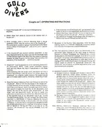
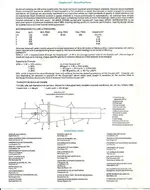
info on the infinity jet, has some calculations/efficiency
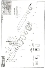
gd5drawing.jpg . gd4instruct.jpg
.
gd3specs.jpg
 

Last edited:
my favorite part about these threads is that the always include pictures of the things that actually work...

yet there will be page after page describing how to make something work almost just as good...

weird.
 

Man you obviously never seen a Schmidt Bazooka Dredge, it's a tri-jet subsurface fluid-bed dredge!

Honestly though subsurface dredges have a massive disadvantage over surface dredges as the recovery sucks and you can't make a real hole. A subbie also needs to stay vertical for optimum recovery. I have a 6" subbie I got for my 4" to start holes aka overburden cannon aim it over into the current not trying to catch fines but if a nugget appears it might get caught LOL... Poor performer in creeks very unwieldy.
 

Last edited:

Top Member Reactions

Users who are viewing this thread

Back
Top