United States Patent 7,182,295 continued:
In prior experiments tests for propulsion were performed at high voltages of 300 kV and even Megavolts. Typically, between capacitive plates two opposite plates are being charged from zero to high voltage. Electrons leave the metal surface on the negative plate and are accelerated towards the positive plate. As the electron accelerates its speed increases steadily to very high values. In an embodiment, the emitter wire layers 1362, 1364, 1366 and ion plate arrays 1350, 1351, 1352 act as these capacitive plates. In an embodiment the Biefeld Brown effect may cause the effective electron mass to act as a real heavier mass. Applying Newton's laws may result in erroneous calculations because the Biefeld Brown effect deals with relativistic speeds within lifters. The higher the applied voltage to the capacitive components, the higher the input energy E=Vq, the less accurate may be calculations based upon Newton's theories.
Einstein's Space-Time warping theories can be more practically applied for the effective mass, total energy and actual particle speeds within a high voltage gradient field. Effective mass at relativistic speeds=m/(1-v.sup.2/c.sup.2)1/2=ym. Total energy=ymc.sup.2. Energy used during acceleration=(y-1)mc.sup.2. 1 mc.sup.2 is equivalent to the energy stored within the mass of particle at rest and is not part of the input energy.
Several explanations can be generated for the above equations.
1. The energy required to move stationary mass m at velocity v is equivalent to that moving a much higher effective mass at velocity v.
2. The energy required to move stationary mass m for a distance d is equivalent to that moving the same stationary mass m for a much longer effective distance than d.
3. The energy required to move stationary mass m for a distance d during time t is equivalent to that of moving the same stationary mass m for the same distance in a much shorter time.
4. The energy required to move stationary mass m at velocity v, is equivalent to the energy required to move the same mass at velocity v, plus an energy doing work against radiation pressure difference (vacuum mod/ether mod/space-time warp.) between the front and rear sides of the particle.
The apparent mass increase is all due to the energy going into the space fabric, and none of it actually increases the real mass of the particle. The mass increase (as shown by points 1, 2, 3, 4) is only a virtual description of the effect best described by point 4.
When a relativistic particle travels through the field gradient between the capacitive plates a space-time warping effect may occur in the space-time fabric. The greater the `effective` mass or energy input, the greater the space-time warping effect. Thus, in an embodiment, the electric-energy lifting panel 1304 may produce its own a gravity field and thereby cause an anti-gravity effect. These particles with relativistic speeds undergo time dilation, that is when viewed from an external inertia reference frame, the particles seem to be going slower, and so energy from outside this frame seems to be going in for a longer time. Even if the effect might be very small, the speed of electrons in electric-energy lifting panel 1304 undergo time dilation, which indicates the occurrence of space-time warping. The same kind of space-time warping created by the Earth's gravity field. The higher the voltage, the greater the field, and the greater the deviation between the electric-energy lifting panel 1304 inertial reference frame to its ambient. The volume of air around the electric energy panel also undergoes mechanical inertia changes and electrical permeability changes.
Embodiments of the electric-energy lifting panel 1304 can still levitate inside a vacuum enclosure. While ion wind propulsion can work in space, it usually assumes that there is argon, krypton, or other noble gas to be used as the propellant. Yet embodiments of the electric-energy lifting panel 1304 may function in a vacuum enclosure with no such gas available for transport.
FIG. 14 illustrates front view an embodiment of the emitter wire air gap and ion plate relationship. As discussed above, the ion plate 1458 may have a bent over top edge 1460. The emitter wire 1456 may be a variety of geometric shape. The emitter wire 1456 generates a corona effect 1484 around the emitter wire 1456. The air gap 1459 generally has a define space but can be control by the control linkage. The air gap 1459 acts as a dielectric between the capacitive plates of the emitter wire 1456 and ion plate 1458. A support strut 1483 may maintain or control this air gap 1459 and thus dielectric effect of the air gap 1459.
Embodiments of the electric-energy lifting panel may change the dielectric material from the air-gap 1459 to another materials used to increase the dielectric capacity. High-K dielectric materials may be used to increase the displacement of electrons in the material to enhance charge transport. The increased dielectric potential of the layered materials also increases the breakdown resistance to allow thinner materials to be used. An embodiment of the electric-energy lifting panel without an air gap as the dielectric may accommodate lower voltage requirements between the ion plate 1458 and the emitter wire 1456. A given level of voltage must exist to create the Ion wind effect. However, the voltage may not have to create the very large e-field gradient, such as 50,000 v, to create a leakage current across such a large void. Therefore, the overall voltage across the device may be reduced, for the same amount of thrust. I
In an embodiment, the electric-energy lifting panel may lift 3 pounds per horsepower. Thus an electric-energy lifting panel consuming 66 horsepower may lift 200 pounds of mass. A lower operating voltage in turn means that a lower-output power-supply can be used for a given amount of current, which increases the overall efficiency. The layered materials of the electric-energy lifting panel having a high-k dielectric material rather than an air-gap may also ease manufacture of the electric-energy lifting panel.
The high electric field between the capacitive plates may act to change the refractive index of the dielectric material. The dielectric constants may increase with refractive index for different materials. The dielectric constant, K, is equal to the sum of the real (E') and imaginary (E'') permittivity of a material and is the square of the refractive index, or K=n.sup.2=c.sup.2/v.sup.2. The effective mass increase factor y, may be related to the dielectric constant K of the dielectric as follows: y=(1-v.sup.2/c.sup.2)-1/2; y=(1-K-1)-1/2.
Thus, the effective increase in energy required to accelerate the particle at relativistic speeds may not be due to an increase in the real mass, but due to the changes undergone by the surrounding medium/dielectric properties. The extra energy involved is being used up to modify the dielectric constant within the dielectric material.
Dielectric materials store energy. Total energy in the accelerating system=(y+1)mc.sup.2. Note the +1 mc.sup.2 is equivalent to the energy stored within the mass of the moving particle and is not part of the input energy. Input energy=ymc.sup.2, where m is the stationary mass, which is a constant. Input energy=(1-K-1)-1/2 mc.sup.2. However, as speed gains up, input energy goes up, but the actual resulting acceleration may go down, until it zeroes at v=c. Thus the unaccounted for energy may be given out to the surrounding space. The unaccounted for energy may be stored within the dielectric (space, air, mica or whatever). A dielectric may be defined by its permittivity, and it is this value which can be expanded or compressed as the energy fills up this space.
Note that in the expression: Input energy=(1-K-1)-1/2 mc.sup.2, the only variables are the energy and the dielectric `constant` which is not constant at all. The dielectric constant K of a capacitor can change with temperature and frequency. The refractive index (n) varies with frequency (and K=n.sup.2). When energy is input into a device containing relativistic speed particles, its dielectric constant (and its refractive index) can change. Of course this will not be the `relaxed` condition of the dielectric, and it will be in a stressed condition, until the internal energy is dissipated, and the dielectric gives back this energy and acquires back its normal permittivity. This process is very similar (actually the same) to the process of charging a capacitor.
A high voltage capacitor is thus changing its internal permittivity with electrical energy input, and thus may be modifying space-time within its plates. From the above discussion, it follows that a change in space-time is normally accompanied by a change in dielectric constant, a change in refractive index, a change in the properties of its inertia reference frame and a change in gravitational field within its plate. In fact, it is known that when an isotropic substance is placed in an electric field, a change in refractive index occurs, which is better known as the Kerr Effect. The effect is quadratic with respect to the electric field strength.
This supports the idea that a capacitor charged at high voltage will gain inertia, not because of its speed or mass, but because of the modified space-time within it. The highest gain in inertia or gravity field will be nearest to the positive plate where most particles would have accelerated to their maximum speeds a thus left the most stressed space-time. The situation can be explained as `elastic potential energy within the space-time fabric` and this potential energy will be present as long as the capacitor stores the energy within its dielectric.
The thrust or lift generated by the electric-energy lifting plate can be higher in asymmetric capacitive electrode configuration. A mass or localized energy field within a highly energized dielectric within a symmetric electric field may not be subject to any external force, other than its own gravity field pointing towards the center of the mass in all directions. Under the Biefeld Brown effect, the thrust is higher in asymmetric electrode configuration. In a symmetric capacitor, the only asymmetry in its energy field is due to the fact that the motion of the electrons at the positive plate is at a higher kinetic energy than that of the electrons leaving the negative plate. This results in very small space-time curvature, with very small interaction with external energy points or masses, resulting in very small thrust. However, a larger space-time curvature occurs for an asymmetric electrode configuration. This asymmetric energy distribution causes generation of space-time elastic stress without the requirement of any particles flowing within the system. This would also explain the fact why a graded dielectric would amplify this elastic stress within such a field. The result of this space-time curvature on masses or energies within the frame (the B--B device) would be similar to a mass entering earth's gravity field. No particles are required to hit the subject, but the subject tends to be accelerated towards the slower time, i.e. the highest energy level. The greatest effect will be obvious on any matter within the field itself, but also on the walls within reach of the electric field force. In case of such a device operating in vacuum, with no mass or walls in the vicinity, the propulsion would be achieved by the space-time curve acting on the surrounding energy within the vacuum (vacuum energy, ether, etc.) which is abundant of high energy cosmic energy, the same energy causing gravity on any planet in the universe.
The Biefeld Brown effect generates elastic potential energy within the dielectric. Efficiency of this mechanism can reach near 100% if the elastic limit of the dielectric is reached on the positive electrode side. The elastic limit of all dielectrics is the same and equates to the condition v=c. Very high efficiencies such as 99% may be possible by using very high voltage to charge the capacitor. At such a limiting voltage we get:
Input energy=(1-K-1)-1/2 mc.sup.2=1/2 CV.sup.2, where C is the capacitance and V=terminal voltage. Another formula for capacitance is: C=(2.times.(1-K-1)-1/2 mc.sup.2)/V.sup.2.
The Biefeld Brown effect can correlate to the mass of dielectric as well as other conventional physics parameters making up capacitance. The above equation shows that at such high voltages, capacitance is related to dielectric mass as well. Both potential energy within the charged capacitor and Earth's gravitational potential energy may use the same mechanism. An embodiment of the electric-energy lifting panel use the electric energy in the capacitive plates to effect a gravity field. If the gradients of the electric-energy lifting panel gravity field and the Earth's gravity field are pointed against each other, then their elastic potential energies can do work against each other. Similar to pressing two springs together and releasing both. The lighter spring will move faster (our craft) as opposed to the `Earth`. There may not be energy conversion in this process since they are both gravitational potential energies. This would imply that:
Electrical input energy=Input energy=(1-K1)-1/2mc.sup.2=1/2CV.sup.2=mgh, where h would be the change in altitude of the powered craft.
This method could eventually obtain efficiencies of over 99% for the conversion of electrical to kinetic energy within any dielectric medium including space. Under a theoretical basis, the craft's maximum speed may not be limited by the ion drift velocity but only by the speed of light.
Corona discharge 1484 (ion current flow) starts earlier then visible corona can be seen. Detailed tests about corona formation were made by Peek in the beginning of last century. Based on his tests he came up with an equation known as Peek's for corona onset voltage. An embodiment of the personal flight vehicle can use these equations in calculating thrust/voltage dependence: V0=g0*r*In(d/r) where g0=30*kV/cm*delta*(1+0.301/sqrt(delta*r)); where r is radius of corona-wire in cm, d distance between wires and delta is a factor depending on air pressure and temperature as delta=3.92b/(273+t); where b is pressure in cm of barometric pressure and t is temperature in degree C.
For example, at d=30 mm and r=0.5 mm, an embodiment of the personal flight vehicle gets V0=14.4 kV, but with 50 gauge wire (0.01275 mm) the emitter wire gets V0 of 2.7 kV. So when the personal flight vehicle uses thin corona wire, the personal flight vehicle may get useable thrust at 10 kV.
FIG. 15 illustrates an embodiment of an electric-energy lifting panel. A spark gap may produce propulsive capabilities. The ion conditioner 1522, such as a laser, can enhance ion conduction of the air. The ion conditioner 1522 acts to increase the amount of conduction current in an ion processing effect propulsion system without increasing the power-consumption. The magnitude of voltage still must be high-enough to create the ion wind conduction current in the first place; however, the ion conditioner 1522 can lower the minimum conduction voltage. Similar to the high K dielectric, the ion conditioner 1522 can lower the operational voltage used in the personal flight vehicle 1502. High voltage ion-wind involves voltages that are enough to cause ionization in the first place. Efficiency curves for ion wind tend to start at the part of the curve where ion-wind begins at around 20,000 volts. If you can visualize a voltage to thrust curve, the curve would start out high and become lower as voltage increases. In other words, you may gain 1 watt's worth of thrust by doubling the voltage, but it costs you 2 watt's worth of input power to achieve one watt of ion wind. Traditionally, most scientists do not try to experiment further up the curve to the part where a high-efficiency exists because air does not typically conduct electricity at those frequencies. However, the ion conditioner 1522 can assist the personal flight vehicle 1502 to operate in these regions of higher efficiency.
The volume of electricity seems to enhance propulsion more than the speed of the electricity (current versus voltage). While increasing voltage does have a positive effect on propulsion, the trade-off in terms of power required to step up to the voltage may not make up for the increased power consumption.
Several ways exist to ion enhance the air envelope around the personal flight vehicle 1502, such as UV bulbs, Lasers, and Microwave-Excitation of the air. Ion enhancing the air envelope can increase the conductance of the air gap. Because the air-gap is a dielectric and the ion enhancement forces more ions through it, a higher-voltage is going to cause a greater number of them than a low voltage. In contrast to typical ion-wind theory, under one ion-wind theory, the volume of current does more work than the voltage that it travels at. The only requirement is that the voltage is high enough to conduct through the air gap. The volume of ions is doing most of the work, not the ions' speed. The ion conditioner 1522 increases the volume of ions as well as lowers the required voltage to stimulate ion wind.
Traditional Ion processing experimenters have indicated that experimentally, 40 kilovolts appears to provide a great deal of thrust compared to 30 kv, however, this is not mathematically supported, and is believed to result from increased conductivity of the atmospheric medium. In other words, since the air essentially functions as a semi-permeable dielectric, the increased voltage has a greatly pronounced effect on conduction-current transfer through the air, which bears the resemblance of being more powerful when in reality it is simply more efficient than the lower voltage.
Extrapolation into low-voltage behavior from previous equations, which were designed for high-voltage research, shows that lowering the voltage to levels considerably below those thought to be possible allows a much greater increase in efficiency than previously thought. Using Saviour's equations, a baseline voltage of 30 kv from an example emitter wire to ion collector plate could produce a performance of 1 g/Watt, and an ion-transport speed of 1.72 cm.sup.2/Vsec. Having established a baseline to compare against, when the value of 115 volts rectified to DC is used instead of 30,000 volts. The overall performance changes to 324.6 g/Watt, which is equivalent to nearly 1 pound per watt, or about 746 pounds per horsepower. Further, adverse X-ray and ionic effect are reduced as the voltage field gradient is lowered.
Ultraviolet photo-ionization occurs at the frequencies of, for example, 1024 nm for O2 and 798 nm for N2, both of these atmospheric air molecules will photo-ionize. Thus, these molecules found in air will then become ready for manipulation by electrical fields in the same manner that similar molecules ionize by high-voltage.
An Excimer-laser can stimulate the air-molecules within the beam radius to become conductive. The conductivity of a lightning channel or any atmospheric plasma--is in fact greater than the conductivity of an equal volume of copper wire. Thus, it is possible to manipulate and direct low-voltage currents of electricity through the atmosphere in the same manner that they are directed through a circuit board by using the appropriate wavelengths of ultraviolet radiation. The ion conditioner 1522 stimulates ion-production and conduction-charge transfer to modify the conductivity properties of air. So, instead of using 30 kilovolts of electricity to stimulate ion-production and conduction-charge transfer, a much greater amount of electricity can be transferred at a much lower voltage, such as 115 volts DC, without the side-effects associated with the traditional Ion processing and Ion-Wind technologies. Further, lower-voltages in Ion processing atmospheric conduction apparatus reduce overall power levels, output heat, and component failure rate.
FIG. 16 illustrates an embodiment of the personal flight vehicle using a laser as an ion conditioner. A laser 1622 creates and steps up the ion field in the air around and between the capacitive plates inside the electric-energy lifting panel 1604. A nitrogen based laser, such as an Excimer laser, that ionizes the atmosphere could be used to reduce the required voltages for useable thrust to, for example, 125 volts. One watt of electricity stepped up to 10,000 volts may not be efficient. Pre-ionizing the operational air around the Personal Flight Vehicle 1604 provides efficiencies of energy. Ultraviolet light can be used to enhance the conductivity of the atmosphere, which can then conduct electricity at otherwise non-ionizing potentials. For example, after laser ion amplification and broadcast by a 193 nm ArF excimer laser, 115 volts may generate up to 2800+grams/watt. Transmitting ions down a laser beam may have one drawback, which is it is difficult to get as much "lifting area" as with the wire-foil combination. Lasers 1622 such as UV-laser diodes, Nitrogen lasers, or CO2 lasers may be used to ion enhance the air. The laser 1622 may be combined with a targeting component to direct such a laser pre-ionizer or ionization amplifier.
In an embodiment, a different approach could involve the use of a short-wavelength UV laser pulse (248 nm) from the ground tower. The short-wavelength UV laser pulse produces a line of photoelectrons between the Personal flight vehicle 1602 and ground. The density of the photoelectrons created by direct three- or four-photon ionization is controlled by the peak intensity of the UV pulse. By contrast, in the case of the CO2 laser, the high field of the laser may lead to an uncontrollable electron-avalanche process. A distinct advantage of the shorter wavelength UV laser pulse is generating plasma having the reduced diffraction. The aperture of the short-wavelength beam on the ground could be at least 40 times less than that needed for a CO2 laser beam.
Three steps occur in the process of using a UV femtosecond pulse to create an ionized air channel. First, the pulse is propagated through the atmosphere to generate photoelectrons. Then, these electrons migrate and multiply in the electric field and induce a local electrical-field enhancement and electron avalanche. This avalanche leads to a completely ionized front or "streamer", moving at speeds up to one-third the speed of light.
The temporal and spatial focusing of femtosecond pulses at a wavelength of for example, 248 nm, can be used to create a narrow elongated needle of photoelectrons in the atmosphere. Two properties of air are particularly interesting at that wavelength. First, the ionizations of cross-sections of oxygen (three-photon) and nitrogen (four-photon) are particularly large, so that less than 50 mJ is required to obtain the minimum photoelectron density of 5.times.10 to the 11th e-/cm squared to initiate a lightning discharge. Second, the wavelength dependence of the index of refraction of air can be used for compression of properly pre-chirped pulses.
Ionizing a column through the air is only the first step. The ionized electrons remain for a few nanoseconds, before attaching to oxygen to form O2 and O-ions. Due to their low mobility, the conductibility of the ionized path is drastically reduced with the substitution of these ions to the electrons. This problem can be solved easily by sending a "photo-detaching" laser beam along the same path as the UV laser. A 0.2-mJ optical-pulse energy at one-half the self-breakdown voltage could be one of the smaller energies used to stimulate the effect. Such a system consists of a Ti: sapphire laser, a negative-dispersion line, a regenerative preamplifier, a large aperture amplifier, and a frequency-tripling assembly.
In an embodiment, the navigation system 1620 mounted on the flip and lock dashboard 1618 may include a control electro-mechanical system. The control electromechanical system coordinates with the tortuous pivot frame 1610 to control the pivoting of the electric-energy lifting panel 1604. The navigation system 1620 may also include a HITS GPS system which tracks the induction stream beamed from the ground based power distribution towers to keep a user on the air-roads. The GPS system relays positioning information and generates a red light and audible signal the operator that a user has wandered outside of prescribed flight lanes.
FIG. 17 illustrates an embodiment of the personal flight vehicle having the flight situation display system. The global positioning system navigation system 1720 may send and receive data from the flight situation display system 1730. The flight situation display system 1730 may be ergonomically designed. The flight situation display system 1730 replaces the old-fashioned instrument panel per the NASA Advanced General Aviation Transportation Experiment (AGATE) cockpit revolution. The display system 1730 is the foundation for NASA's Highway in the Sky (HITS) initiative, which is developing affordable glass cockpits for single-engine, single-pilot airplanes by the year 2001. The HITS display projects a pre-planned course "highway" for the pilot to follow, instead of gauges and dials for the pilot to interpret and synthesize into a mental picture of the airplane situation. The graphical display system 1730 includes a two-panel display of Global Positioning System (GPS) position and attitude, course, weather depiction, and aircraft track and performance. The integrated flight display system 1730 provides the pilot with an intuitive pictorial for situational awareness, and with a system that is affordable for a wide spectrum of general aviation aircraft. The pilot will use the highway display to guide and control the airplane intuitively.
In an embodiment, the frame the personal flight vehicle 1702 and the electric-energy lifting panel 1704 may be of composite structure, Graphites, bonded laminates and or similar materials. The electric-energy lifting panel 1704, flight suit 1732, and helmet 1731 contain Electro Magnetic Field shielding.
FIG. 18 illustrates an embodiment of the personal flight vehicle having an electric-energy lifting panel located under the user. An embodiment of the personal flight vehicle 1802 may have an electric-energy lifting panel 1804 located under the user. In an embodiment, the personal flight vehicle 1802 may produce ozone gas to help fill the Earth's disappearing ozone layer. The production of Ozone is a by-product of the kinetic interaction of electricity of sufficient voltage levels with air-molecules. In embodiments that use higher voltages, the increase in ion conduction reduces ozone production compared to the same voltages without increased ion conduction. Further, in embodiments that use higher voltages, added shielding 1885 reduces electromagnetic-interference between the personal flight vehicle 1802 and nearby electrical-equipment.
The pitch, roll and yaw process may be accomplished by either, varying energy to sections of the energy plate or triggering compressed hydrogen gas bursts through thrusters on the backpack or triggering hydrogen thruster gas combustion through thrusters on the back pack or via a small electric fan mounted on the back pack which can be directed via cables or servo motors. A joystick which can be plugged into the waist yoke at a connector on either the right, left or center of the yoke may be the main control mechanism.
FIG. 19 illustrates an embodiment of a single layer of concentric rings of an ion plate array. Each ion plate 1950 may be formed in a concentric ring or a different shape.
FIG. 20 and FIG. 21 illustrate an embodiment of a single ion plate bent over at the top edge of the plate. As discussed, an ion plate 2058 bent over at the top edge of the plate 2060. In an embodiment, the ion plate collector-voltage is set below the ground-voltage level of the environment to reduce static charge build up.
FIG. 22 illustrates an embodiment of a portion of the electric-energy lifting panel changing the air gap between the emitter wire layer and ion plate array. Several mechanisms exist to change the air gap 2259 between the emitter wire layer 2266 and ion plate array 2252.
FIGS. 23 28 illustrate various views of an embodiment of a personal flight vehicle. In an embodiment, a version of a personal flight vehicle 2302 that has an enclosure for a user to sit in may employ the electric-energy lifting panel which has two capacitive plates with different geometric dimensions to generate a net-directional force. An embodiment of the personal flight vehicle may have the following components: one or more electric-energy lifting panels 2304 having a first capacitive plate 2306 and a second capacitive plate 2308; a tortuous pivot frame 2310; one or more ion conditioners 2322, such as ultraviolet-light emitting bulbs, an Excimer laser or other similar device; a gaseous propulsion system 2324; one or more air-breathing rockets 2326 with hydrogen fuel support 2328; a flight situation display system 2330; a global positioning system navigation system 2320; Uncondensed hydrogen cylinders 2334; fuel cells 2338; an inductive transformer stack 2340; thermal slipstream enhancers 2380, Laser/ionization power module 2990, as well as other components.
When high voltage (-30 kV) is applied to a capacitor whose electrodes have different physical dimensions, the capacitor experiences a net force toward the smaller electrode. This operates on capacitors of various shapes.
The order of magnitude of the net force on the asymmetric capacitor may be estimated assuming two different primary mechanisms of charge conduction between its electrodes and a variety of secondary mechanisms. The primary mechanisms are ballistic ionic wind and ionic drift.
Calculations indicate that ionic wind may be at least three orders of magnitude too small to explain the magnitude of the observed force on the capacitor. The ionic drift transport assumption leads to the correct order of magnitude for the force. A thermodynamic treatment of the net force on an asymmetric capacitor also contributes to the effect. The thermodynamic treatment takes into account plasma effects: ionization of gas (or air) in the high electric field region, charge transport, and resulting dynamic forces on the electrodes. There may be some varying degrees of interdependence of the ion force on gas pressure, gas species and applied voltage.
When a high voltage (-30 kV) is applied to the electrodes of an asymmetric capacitor, a net force is observed on the capacitor. Asymmetric may mean that the physical dimensions of the two electrodes are different, i.e., one electrode is large and the other small.
In an embodiment, the largest force on the capacitor is in a direction from the negative (larger) electrode toward the positive (smaller) electrode. The force on the capacitor exceeds its weight. There is a force on the capacitor independent of the polarity of applied voltage. The greatest force on the capacitor is created when the small electrode is positive. The effect occurs in a dielectric medium which is air but future applications for space vehicle propulsion could be operate in a vacuum as well.
In the inverse effect: when a dielectric medium is made to move between high voltage electrodes, there is a change in the voltage on the electrodes. The asymmetric capacitor does show a net force, even in vacuum. Responsibility for the net force on an asymmetric capacitor may be dependant on whether the asymmetric capacitor is in a polarizable medium, iii air, or in vacuum. A net force is exerted on the capacitor when a high D.C. voltage is applied to the electrodes. With many different types of geometries, a common feature may be that one electrode is thin and the other very wide (asymmetric dimensions). Also, a suspended wire, representing a capacitor with the second electrode at infinity, showed lift.
In an embodiment, the force on the capacitor generally appeared in the direction toward the small electrode--independent of the orientation of the capacitor with respect to the plane of the Earth's surface. The significance of this observation is that the force may have nothing to do with the gravitational field of the Earth, and may have nothing to do with the electric potential of the Earth's atmosphere.
In an embodiment, the thin emitter wire electrode must be at a sufficient distance away from the ion plate so that arcing does not occur from the thin wire electrode to the foil, at the operating voltage. The edges of the capacitor, nearest to the thin wire, may be rounded over and pointing towards the ground to prevent arcing or corona discharge at sharp capacitive plate edges (which are closest to the thin wire).
The capacitor showed improved lift when rounded foil was put over the foil electrode closest to the thin wire, thereby smoothing-over the sharp foil edges. Physically, this means that the radius of curvature of the foil nearest to the small wire electrode was made larger, creating a greater asymmetry in radii of curvature of the two electrodes.
In an embodiment, when operated in air, the asymmetric capacitors exhibit a net force toward the smaller conductor and this force is independent of the D.C. voltage polarity. The detailed shape of the capacitor seems immaterial, as long as there is a large asymmetry between the characteristic size of the two electrodes.
Sonic manifestation may be produced in operation which appears as a peculiar hissing sound with pitch varying with the applied voltage. The personal flight vehicle may use sonic sensors as part of the flight control system to verify proper operation of the craft. This sound generally increases with air ionization or conditioning.
In an embodiment, the propulsion force may come from several different forces. The first is that there exists an ionic wind in the high field region between the capacitor electrodes, and that this ionic wind causes the electrodes to move as a result of the momentum recoil. Additionally, a drift current may exist between the capacitor plates. In this scheme, the order of magnitude of the force on an asymmetric capacitor is correct, however, this scheme may contribute as a scaling theory. Additionally there is a thermodynamic treatment of the force on an asymmetric capacitor
The most common explanation for the net force on an asymmetric capacitor invokes ionic wind. Under a high voltage D.C. bias, ions are thought to be accelerated by the high potential difference between electrodes, and the recoil force is observed on an asymmetric capacitor. Consider a capacitor that operates at voltage V. Charged particles of mass in, having charge q, such as electrons or (heavy) ions, are accelerated to a velocity v, having a kinetic energy
Another possibility is that heavy ions (from the air or stripped off the wire) are responsible for the ionic wind. As the heaviest ions around, assume that Cu is being snipped from the wire. Using Cu for the ions, the mass of the ions is 63.55 mi, where 63.55 i5 the atomic mass of Cu and MR is the mass of a proton. The force of the ionic wind this effect will operate in vacuum, and may contribute to the overall force on a capacitor.
One can compute an upper limit to the force on a capacitor due to ionic wind effects. Ionic wind is a ballistic flow of charges from one electrode to the other. There is another type of classical transport: drift of charge carriers in an electric field. In the case of drift, the carriers do not have ballistic trajectories, instead they experience collisions on their paths between electrodes. However, due to the presence of an electric field, the carriers have a net motion toward the opposite electrode This type of transport picture is more accurate (than ballistic ionic wind) for a capacitor whose gap contains air.
The positive and negative electrodes of the capacitor are charged and that these charges experience different forces, because the electric field surrounding the capacitor is non-uniform. The electric field surrounding the capacitor is created by the potential applied to the capacitor electrodes and partial ionization of air into positive ions and electrons. These charge carriers experience drift and diffusion in the resulting electric field. The high voltage DC power supply or main energy source supplies the energy that is dissipated by transport of carriers in the electric field. The electric field is particularly complicated because it is the result of a steady state: the interplay between the dynamics of ionization of the air in the high-field region surrounding the electrodes, and charge transport (drift and diffusion of positive and negative carriers) in the resulting electric field.
If the capacitor is surrounded by vacuum (rather than a dielectric, such as air), the net force F on the asymmetric capacitor can be computed by the sum of two surface integrals, one over the surface of the positive electrode and one over the surface of the negative electrode. An alternative but equivalent picture is that the capacitor is an electric dipole in an nonuniform electric field that it has produced, and the ions form an electronic maple syrup, due to their high mass and resulting low mobility.
The energy flow from the positive corona wire to the negative foil below may not be a straight line of energy but an outflowing balloon shaped cascade of energy that is moving towards the lower negative ion-plate. One embodiment causes the energy to miss the lower ion plate and to create thrust by flying past it and downwards in increasing power.
Therefore, the physical picture is that in the high field region the electrons, with their high mobility, are swept out by the electric field, toward the thin wire electrode and cause dynamic screening of the potential (Dielectric screening due to polarized air atoms will also take place.) However, the massive (probably positive) ions are less mobile and are left behind in a plasma surrounding the thin wire electrode. An asymmetric capacitor may have a mass that is two orders or magnitude greater. Consequently, drift of electrons may not fully explain the observed force on the capacitor.
FIGS. 29 33 illustrate various views of an embodiment of a personal flight vehicle. In an embodiment, a version of a personal flight vehicle 2900 that has an enclosure for a user to sit in may employ the electric-energy lifting panel which has two capacitive plates with different geometric dimensions to generate a net-directional force.
As noted above, an alternative to using the value of electron mobility is to use the smaller value of ionic mobility. This will lead to a larger force because the force is inversely proportional to the mobility.
When a high voltage is applied to the asymmetric capacitor, for example, positive voltage on the thin emitter wire layer and negative voltage on the ion plate arrays, the high electric field around the thin wire ionizes the atoms of the air. There is comparatively little ionization near the ion plate arrays due to the lower magnitude electric field near the ion plate arrays. The ionized atoms around the ion plate arrays form a plasma, consisting of charged electrons and positively charged ions.
The electron drift current leads to a force on the capacitor that may be too small to fully explain the effect on the capacitor. Using the value of mobility appropriate for (nitrogen) ions leads to a force magnitude in agreement with the reality of the effect.
Note that the force given scales inversely with the mobility p. If the ions are responsible for providing the required small mobility, then the idea is that the ions are like a low-mobility syrup, which provides a large space-charge to attract the negatively charged ion plate arrays electrode. As soon as the ion plate arrays electrode moves toward the positive ion cloud. Another positive ionic cloud is set up around the thin emitter wire electrode, using the energy from the voltage source. In this way, the dipole (asymmetric capacitor) moves in the non-uniform electric field that it has created.
The force, generated on an asymmetric capacitor, can be described by the thermodynamics of a fluid dielectric in an external electric field produced by charged conductors. The (partially ionized) air between capacitor electrodes is the fluid dielectric. Although the air is partially ionized, we assume that this fluid dielectric is close to neutral on the macroscopic scale. The charged conductors are the asymmetric electrodes of the capacitor. The batten provides the charge on the electrodes and the energy sustain the electric field in the air (dielectric) surrounding the capacitor electrodes.
The system may include several parts: the partially ionized air dielectric, the metal electrodes of the capacitor and the battery (voltage source), and the electromagnetic field. The battery/DC power supply in the remote power broadcast is simply a large reservoir of charge. The total momentum including the electromagnetic field of this system may be constant.
As far as the electric field is concerned, its total momentum changes little during the operation of the capacitor, because the field is in a steady state; energy is supplied by the battery (charge reservoir). So the personal flight vehicle sets the rate of change of field momentum to zero, giving a relation between the force on the electrodes and the dielectric:
The thermodynamic theory of the net force on a capacitor that is immersed in a nonlinear dielectric fluid, such as air in a high electric field. The main result for the net force on the capacitor is given in Eq. The thermodynamic theory uses the dielectric properties of the gas surrounding the capacitor plates. The personal flight vehicle uses a control mechanism to manage the high-field dielectric properties of the fluid, which is air in this case.
In an embodiment, Cesium ions can be introduced into the operating air (fluid) envelope of the aircraft to provide additional thrust.
FIGS. 34 and 35 illustrate electric-energy lifting panels in the shape of a three dimension triangular sphere. The electric-energy lifting panels 3404 in the shape of a three dimension triangular sphere can be used as the outer shell of the personal flight vehicle or as steering pods with separate addressing of each triangular section for steering. The corona wire-ion plate arrays form in each triangular section 3484. All of the triangular sections 3484 assemble to form a Buckminster Fuller geodesic dome or sphere.
While some specific embodiments of the invention have been shown the invention is not to be limited to these embodiments. The invention is to be understood as not limited by the specific embodiments described herein, but only by scope of the appended claims.
United States Patent 7,182,295
http://patimg2.uspto.gov/.piw?
 air scooter II.webp25.9 KB · Views: 620
 air scooter II 13.webp41.1 KB · Views: 644
 air scooter II Specifications.webp22.9 KB · Views: 623
 air scooter II 10.webp82.3 KB · Views: 1,379
 air scooter II 9.webp53.8 KB · Views: 592
 air scooter II 8.webp10.9 KB · Views: 824
 air scooter II 6.webp49.6 KB · Views: 631
 air scooter II 5.webp1.7 KB · Views: 718
 air scooter II 4.webp3.2 KB · Views: 715
 air scooter II 3.webp3.4 KB · Views: 723
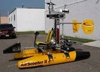 air scooter II 2.webp6.6 KB · Views: 722


