Jim Hemmingway
Hero Member
- #1
Thread Owner
Phase Measurement and Magnetic Susceptibiltiy
Introduction
I’ve organized some notes on the subject that some members may find helpful. We’ll take a look at target ID, ground phase and magnetic susceptibility. Lets do a quick, simple review about what is happening behind the scenes as we swing a VLF searchcoil over the ground, followed with a discussion about target ID and factors that influence it. A final section looks at practical applications of ground phase and magnetic susceptibility measurements. Please keep in mind that what you get here is my understanding of this topic only. You may have something to add to the discussion, so please do so and let’s ensure that everyone can benefit from it.
Background Review
The searchcoil contains both transmit and receive windings. An electric current is passed through the transmit winding to create an alternating electromagnetic field around the searchcoil. This electric current is reversed back and forth thousands of times per second. How often this occurs per second is referred to as a unit’s operating frequency. Gold units generally have higher frequencies compared to coin hunting units. Higher frequencies are more sensitive to smaller gold, but are more susceptible to ferromagnetic ground mineral effects.
The transmitted electromagnetic field will induce an electric current on a metal target within its range and this electrical phenomenon is called induction. The target now generates it’s own electromagnetic field. The target’s electromagnetic field results in the formation of a secondary electromagnetic field on the searchcoil’s receive winding. This is what constitutes a target signal and this signal information is amplified and processed by the detectors circuitry / software package to ultimately provide key information to the user.
Phase shift represents a time delay with the return signal when compared to the transmit signal, a result of a given target's inductance and resistivity. Phase shift increases as target conductivity increases. Thus a silver quarter has a large phase shift while a nickel has a comparatively smaller phase shift. Phase shift is predictable for many categories of targets, and this is especially true of manmade targets such as coins.
Some ferromagnetic targets have little or no conductivity and little phase shift. These include non-conductive iron minerals found in most soils. They distort the searchcoil’s magnetic field and mask weaker signals from small or deeper targets. A result is that a target may not be detected, or if detected it may be incorrectly identified. Ferromagnetic minerals are able to return a strong signal to a searchcoil’s receive winding, often several orders of magnitude stronger than signals from typical small metal targets. A ground balance control is adjusted to minimize or cancel signals from these soil minerals.
The main thing to recognize is that a metal detector regards soil or rocks as just another “target” to be measured in terms of phase shift, and assigned a numerical value on a phase scale. For user convenience, the phase range measurements are reorganized and displayed in the form of VLF target ID for a range of target conductivities, while the soil mineral phase range measurements are displayed numerically on a separate calibrated ground balance scale on some prospecting capable units.
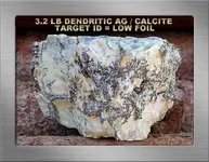
The next section discusses target ID primarily as it applies to rocks and minerals, the physical or chemical factors involved, and the ground conditions that affect a rock’s target ID. The specimen depicted below is a fine example of a dendritic structure. Structure plays a key role in determining target ID for most of the silver we recover here in northeastern Ontario’s silverfields.
Target ID, Ground Phase & Magnetic Susceptibility
(a) Target ID reliability depends on ground conditions, a targets physical / chemical make-up, and effective detector operation.
An improperly operated detector impacts target ID reliability. Here are a few points to keep in mind. (a) Correct coil sweep speed enhances target ID and detection depth. (b) Avoid lingering over a target with autotrack ON, or disable it when assessing a signal. (c) Keep the gain or sensitivity control adjusted to EMI / ground conditions for reliable target ID. Operating the gain at the fringe of instability leads to erratic, unreliable target ID. (d) Ensure the detector is always properly ground-balanced. This is especially important over higher magnetic susceptible substrates, otherwise ground noise will increase and detector performance will suffer.
Many factors come into play with various nuggets and ores to determine where these will locate on target ID readouts. These include the type of metal, the purity, the type of inclusions or alloys, shape, size, structure, and profile to the coil. Structure refers to how the silver or gold is formed, for example plate, disseminate or particulate, nuggety or massive, sponge, and branching or what is otherwise described as a dendritic structure.
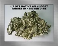
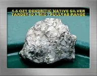
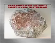
Below are two comparable examples. The first is a variable but solidly structured native silver nugget. It is good purity and free of mineral inclusions, yielding a target ID in the silver dime range. The second specimen is a similar size and general shape. It looks to have similarly pure native silver free of inclusions as well. However in this instance the native silver has an intricate branching or what is technically described as a dendritic structure… that effectively restricts the target ID to the mid-pulltab range.
Ground conditions play a key role with how effective target ID will be at any given site. Ground factors that directly impact target ID include magnetic susceptible iron minerals, soil moisture, and disturbed or undisturbed ground conditions. The proximity and effect of ferrous and non-ferrous metals to a given target signal is a primary factor affecting target masking and target ID that has been discussed in detail in other articles and hence will be omitted here.
Increased magnetic susceptible iron mineralization can play a critical role in target ID. High magnetic susceptible iron minerals reduce electromagnetic field (EMF) penetration into the ground, thereby decreasing target ID depth. These magnetic minerals further compound target ID by distorting target signals. As the non-conductive iron mineral magnetic susceptibility or severity increases, target ID reliability decreases. In extreme ground, target ID is unreliable.
Some soils become more reactive as soil moisture increases. This phenomenon can reduce EMF penetration and play havoc with target ID. Some experts attribute this condition to enhanced soil mineral ionization resulting from increased soil moisture content. Soil moisture beyond “compactive” soil conditions slightly decreases detection depth in my area, a brown clay based soil that happens to be marginally dominated by magnetite. Let’s look at a documented soil sample that is representative of soils commonly encountered throughout the southeastern states.
I have a soil sample lab report from a major manufacturer. It provides an analysis of a “reddish” soil sample submitted by a friend residing in a southeastern state. It concludes the soil in a dry state qualifies as “bad ground” but well within the ground rejection range of their current detector models. The engineer recommended that soil type should only be searched when in a dry state. Below is a direct quote about that same red soil in a wet state.
“When wet the sample becomes very had ground, difficult to reject and or penetrate. This type of iron oxide, because of its consistency, achieves a solidity or connection between iron particles making it much harder to reject when wet.”
The report does not specify the iron mineral, but the culprit is undoubtedly maghemite. We can see why the relic hunters in parts of Alabama, Georgia, Tennessee, North Carolina and Virginia have such a difficult time searching these red soils with VLF units. Target depth is reduced, and target ID is practically useless in some areas especially when the soil is wet.
Searching mine tailings can sometimes equate with searching in “disturbed ground” for any number of reasons. Disturbed ground conditions cause many VLF units to lose some detection depth and struggle with target ID. A result is that good targets even at modest depth are more likely to be identified as iron. Science seems uncertain as to what causes this effect but many postulate that it results either from the loss of electrical alignment or continuity within the soil, or perhaps by the disruption of the magnetic fraction of a soil’s constituents. Many hobbyists relate this phenomenon to a loss of the so-called “halo effect”.
When searching any of the ground conditions described above, operating in the all-metal motion mode is normally your best operating choice. When a target is located, the best procedure with all but very shallow targets is to remove a good portion of the overlying material and recheck target signals. If these continue to indicate iron as you get near to the target, then chances are you can move on. I don’t trust discrimination under such conditions, especially when dealing with very small targets. They tend to read as iron, but it’s your choice to make.
(b) Ground Phase
Lets define ground phase measurement as a weighted-average phase measurement of all soil minerals under the searchcoil at any given sampling point. Ground phase can be viewed as a ground "target ID" measurement based on phase shift similar to any other target ID measurement. What is the significance or usefulness of the ground phase value?
The ground phase can be used for several applications we’ll discuss later, but its primary value is to adjust the ground balance control to effectively cancel out interfering ground signals. The ground balance control should be viewed as a separate discrimination control for this purpose. Proper ground balance results in improved detection depth, more accurate target ID, and more stable operation. That said, keep in mind that ground minerals continue to inhibit EMF penetration and warp the EMF despite proper ground balance. Ground balancing permits us to detect targets to the best of a given unit’s ability within the constraints imposed by ground minerals. This explains why better depth can be had in light soil minerals as contrasted to reduced depths experienced over increased magnetic susceptible soil minerals.
A full-range ground balance scale positions salt at the lower conductive end of the scale and magnetite occupies the most elevated non-conductive range of the scale. All other ground ‘targets’ lie somewhere in-between these ranges on the GB scale. Have a look at the information below. It provides a correlation between soil types and ground phase measurements. These are pretty much taken verbatim from various sections of the F75 manual.
GB 0 to 10 = wet salt and alkali
GB 5 to 25 = metallic iron. Very few soils in this range, you are likely balancing over iron metal.
GB 26 to 39 = occasional salt water beaches, but very few soils in this range
GB 40 to 75 = red, yellow, and brown iron-bearing clay minerals
GB 75 and up = magnetite and other black iron minerals
Many lighter colored clays or loams will normally range between GB50 and GB80, whereas red clays will generally range from GB35 to GB55. Gravelly or sandy soils will tend to range in the GB75 to GB95 range. As an overview the manual further states that the more highly weathered, oxidized, or finely grained the soil is, the lower the numeric GB reading will generally be. These represent generalizations based on phase measurements of many soil samples.
So, we can see that ground phase measurements have associations with ground types. A similar relationship generally applies to specific non-conductive iron mineral types as well. However, ground phase measurements on various non-conductive iron minerals do overlap. Although the type of mineral is much the weightier factor, ground phase to some extent also considers iron mineral “amounts” particularly with respect to where mixtures of maghemite and magnetite exist in the same soil.
In short, the amount of a given substance can also contribute to where the phase measurement reads. To support this statement for example, magnetite and maghemite are both highly magnetic susceptible. However, they occupy distinctly different regions on the ground balance scale. Magnetite occupies the upper end of the ground balance scale whereas maghemite generally occupies the middle portion of the ground balance scale. But mix them in equal portions or amounts and that mixture will result in a ground phase measurement that falls between the ground balance range each substance separately occupies.
This ground balance readout resulting from the magnetite / maghemite mixture just described lies within a range commonly occupied by other non-conductive iron minerals. A good example is the iron mineral called “goethite”. Goethite is prevalent nearly everywhere in northern latitudes. It’s a common constituent in brown soils. The key difference is that most iron minerals such as goethite are only mildly magnetic susceptible when compared to similar proportions or amounts of either maghemite or magnetite either separately or mixed-in together in a given soil as commonly occurs.
(c) Magnetic Susceptibility
Magnetic susceptibility in a metal detecting context refers to the ability of a soil’s iron minerals to attract a magnetic field. The “follow the black sand” feature on the GMT, similar to the Fe3O4 bar graph on the F75 or other units, measures the strength of the ground’s magnetic susceptibility. This measurement is expressed as an equivalent percent volume of the non-conductive iron oxide magnetite. This is a convenient standard that places all magnetic susceptible iron minerals present in a soil into an easily understood context. It measures a soil’s magnetic susceptible strength regardless whether magnetite is present or not, although that would be a highly unlikely scenario.
What contributes to magnetic susceptibility? Once again, both the type and amount of various iron minerals determine a soils magnetic strength. Consider a soil that is dominated by goethite. Goethite has a weak magnetic susceptibility. But if we consider a different type of iron mineral, for example either magnetite or maghemite, in the same amount or quantity in a soil, the magnetic susceptibility is many times greater than is an equal amount of goethite. Therefore to reiterate, always keep in mind that the Fe3O4 bar graph measurement is entirely about the strength of a soil’s magnetic susceptibility.
If we understand the concepts as defined above, (a) it should be clear that ground phase and Fe3O4 readings are two distinctly different measurements with entirely different implications, and (b) we are unlikely to get entangled too much in debates about “types and amounts”. Keep in mind these “types and amount” descriptions were used in related manuals as a very simplified means of describing the use of these features and necessarily are addressed in part to newcomers to the hobby. A result is that some confusion has ensued.
In the Field
As described below, (a) the ground (phase) balance can be adjusted to assist in evaluating rock samples and (b) plays the key role as to whether an iron mineralized rock signals as a negative or a positive hot rock. Magnetic susceptibility is a convenient measurement to indicate how well a VLF unit will perform over a given soil, and can be used to identify shallow black sand deposits. Used in combination with ground phase measurement, the presence or absence of magnetite and maghemite dominant soils can be identified.
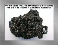
We’ve referred to magnetite many times and will do so again. Here is a photo of this mineral in crystalline form for newcomers to the hobby. Most often it is located in the form of black sands. Magnetite, a non-conductive iron oxide, is an abundant negative hot rock in my area that gives the well-known “boing” signal so familiar to electronic prospectors using VLF units in the motion all-metal mode. If the ground balance control is advanced above a magnetite sample’s ground balance compensation point, that sample changes from a negative hot rock “boing” signal to become a powerful, positive hotrock “zip zip” signal. Magnetite such as you see below will easily max the Fe3O4 reading on the F75.
(a) Ground Mineral Scenarios
As noted above, ground phase measurement can be used in conjunction with the Fe3O4 readout to identify some ground mineral scenarios. They can be used to identify both magnetite and maghemite where they are the dominant fraction of a substrate’s non-conductive iron mineralization either acting in unison, or acting individually. Let’s look at a few examples…
Some operators successfully apply the magnetic susceptibility readout to locate shallow blacksand paystreaks. Frankly, I don’t use the feature for this purpose as my pursuits lie in other directions. I suggest looking for swings in both the ground phase and Fe3O4 readouts. For example, let’s say we are searching an area with GB readouts around GB70 and a fairly light Fe3O4 readout. We experience an abrupt phase swing up into the high GB80’s accompanied by a sharp increase in the Fe3O4 readout. These readouts together indicate that a black sand deposit that may or not contain precious metal values has been located.
Another example: Let’s say we’re out searching the Ontario outback with a ground balance reading at GB75. The Fe3O4 meter reads quite mildly. We enter an area where these readings abruptly change. Now the ground balance reads at GB52 and the Fe3O4 meter has increased into the moderately high or even higher levels. These readouts indicate we are over a “burn” area where the soil is dominated by maghemite. Burn areas can be vast because of past forest fires. The heat generated from fire is sufficient to oxidize lower oxidation state (reduced Fe2+) iron minerals such as magnetite (actually formulated as Fe-Fe2O4, a ferrosic oxide) and other iron minerals into an oxidized ferric (Fe3+) form such as maghemite.
This same oxidation process occurs by means of natural processes as well. For example, small grains of magnetite exposed to the elements can “rust” into a maghemite form. Many of us have seen these “rusty” deposits in magnetite. Another example, the same natural weathering / oxidation process applies to basalt. The iron minerals contained within basalt include magnetite and as these are exposed to weathering over time they can oxidize to form maghemite.
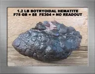
Incidentally, maghemite may be mistaken for similar appearing hematite. The difference to metal detectors is quite distinct. Hematite has a very mild or weak magnetic susceptibility and generally ground balances between 60 and 75 on the GB scale. As a result, it has very little effect on metal detectors. Maghemite is a different matter. Its GB compensation point normally occupies the middle of the GB scale, depending partly on purity, but its magnetic susceptibility is many times greater. Maghemite affects metal detection target ID and depth similar to magnetite, although magnetite is the more magnetic susceptible of these two substances.
A final example, let’s say we’re out detecting an area where the ground phase reads moderately say GB65 to GB70 but we notice the Fe3O4 meter reads quite high indicating a strongly magnetic susceptible soil. We can conclude we are searching an area where there is a good mix of both maghemite and magnetite. There is a separate possibility if yellow clays dominate the area, but otherwise no other conclusion fits this scenario.
(b) Hot Rocks
General Discussion
Our discussion initially refers to VLF responses to hotrocks using the motion all-metal (autotune) mode. Hotrocks are encountered as (a) non-conductive iron mineralized rocks or (b) as electrically conductive hot rocks, usually in the form of sulfides, arsenides, and graphitic rocks in my area. Both hotrock types respond to VLF metal detectors. We’ll discuss non-conductive hotrocks first, followed by a brief discussion about conductive hotrocks. We’ll limit our example of conductive hotrocks to a commonly encountered iron sulfide here in northeastern Ontario’s silver country called pyrrhotite.
Non-conductive iron mineralized hot rocks present themselves with one of two distinct responses to a metal detector. They will either respond with a positive target signal, or a negative “boing” signal due to autotune threshold “overshoot” reaction to a “negative” hot rock. A positive hot rock will have a ground balance compensation point below our operating GB setting, whereas the negative hot rock will have a ground balance compensation point above our operating GB setting.
The negative hotrock “boing” signal directly results from using a motion all-metal (autotune) mode. The autotune initially goes quiet over the rock but struggles to recapture its threshold level as the coil sweeps past the rock. In doing so, it “overshoots” the threshold level briefly and yields an audio response. Thus, as the coil is swept over a negative hotrock we get the familiar “boing” signal. By contrast, when using a true non-motion all-metal mode, negative hotrocks passed across the coil will simply cause the detector threshold response to go quiet. Magnetite within a rock structure is normally responsible for negative hot rock responses. These are fairly easy to recognize and can be readily ignored.
Small positive hotrock signals can be frustrating to electronic prospectors because their signals sometimes mimic nugget signals. Stronger signals can target ID in the upper portion of the iron range, as do many small nuggets concealed in highly mineralized ground. Fortunately, hotrocks that respond to metal detectors tend to reside very close to or on the surface and lose their signal quickly as the coil is elevated. In fact this is one method, in conjunction with reduced gain… to mitigate hotrock signals. Maghemite, a highly magnetic susceptible, red-brown iron oxide, is normally the culprit responsible for small “red hot” positive hot rock responses.
Techniques to Mitigate Nuisance Hotrock Signals…
The foremost option is to learn to identify and consequently ignore most hotrocks in your area. As noted, most non-conductive iron-mineralized hotrocks can only exist at or near the surface… their signals tend to quickly subside with coil elevation compared to similar size metallic targets. They can usually be identified at a glance and kicked away. Unfortunately in my area non-conductive diabase hotrocks occur in very large sizes up to several hundred pounds and cannot be ignored or kicked away. They often completely dominate the substrate at some sites, and magnetic strengths and ground phase are individually somewhat variable. Those that produce signals must be neutralized such that adjacent or underlying metallic signals can be more easily identified. Obviously ground-balancing PI units are an excellent alternative to VLF units in tolerably low trash areas here.
In higher magnetic susceptible iron mineralizations, one must either contend with hotrocks individually as described later, or apply some amount of iron discrimination to be determined in the field for the hotrock types encountered. The more persistent positive signals may require discrimination settings slightly above the level required to eliminate small bits and pieces of metallic iron. Just how much discrimination is required really does depend on how the detector model and operating mode employed processes these signals. For example, the F75 will eliminate all negative hotrock signals, regardless of magnetic susceptible strength, at zero discrimination in all discrimination modes. Positive signals produced by those same high magnetite-bearing rocks require a discrimination setting of “1” in DE / PF modes and a maximum iron setting of “15” in JE mode. Positive signals are rarely encountered with these rock types unless searching in substrates dominated by them, for example... our massive diabase beds here in northeastern Ontario's silver country.
The level of discrimination required may also eliminate some small nuggets that fall into a similar conductive range, and possibly deeper larger nuggets on the threshold of detection depth in highly mineralized substrates. Check your discrimination adjustments… bury a suitable test nugget at a reasonable depth… and determine the effect of your discrimination settings on it.
In lower magnetic susceptible iron mineralizations, there is no reason why discrimination cannot be used as described above. But many operators prefer to ground balance to an area’s prevalent hot rock type and search at that GB setting if it is satisfactory. In lower mineral conditions this is acceptable practice because GB settings have wider windows of utility than exist with higher magnetic susceptible mineralizations where spurious ground noise will be generated as a result of even minimal offsetting of GB values. So while this technique in such conditions will leave you improperly ground balanced to some extent, either above or below that required for the surrounding terrain depending on the hotrock type… it is not nearly so critical as it would be if used over more severe ground minerals. Check your GB adjustments, bury a suitable test nugget at a reasonable depth… and determine the effect of using offset ground balance settings on it.
Autotracking can play a useful role over variable ground and areas littered with hotrock signals or noise. For example detecting streamrun cobbles, autotracking conveniently serves to reduce or eliminate such signals. But remember to disable the autotracking feature when evaluating potentially genuine target signals to avoid possibly canceling such signals. In abundant hotrock areas where the target size is sufficiently large to respond and trash levels are tolerable, a suitable ground-balancing PI unit is a more likely alternative.
Over any normally encountered ground mineralization conditions in prospecting country, particularly where hotrocks are not terribly plentiful, some prefer to use the “GROUNDGRAB” or sometimes called the “GRAB” or “FASTGRAB” feature available on many of the modern prospecting-capable detectors to assist with target signal evaluation. The FASTGRAB feature simplifies searching hotrock areas properly ground-balanced in the all-metal motion mode because it takes only a moment to check out a suspect hotrock signal and then quickly re-balance to the ground and continue searching. If an unidentified ‘fastgrabbed’ rock continues to produce a signal, it should be investigated further.
For example, our positive diabase hotrocks that produce good strong signals will read consistently in the upper iron range at target ID “14” on the F75. But when ground-balanced using the GROUNDGRAB technique, they lose their positive signal, their target ID disappears, and there is always a small reduction in the ground balance readout. Other positive non-conductive iron-mineralized hotrock types in this area react similarly, but experience more variable GB reductions according to the ground phase compensation point for any given rock.
As we’ll discuss later, we can bench test suspect rocks by adjusting the ground balance control to an appropriate setting whereby both types of non-conductive iron mineral hot rocks will give a negative threshold response regardless of their phase compensation point or magnetic susceptibility.
Conductive hot rocks respond with positive target signals to a VLF metal detector. The most frequently encountered electrically conductive rocks in Ontario’s silver country result from sulfide or arsenide ore responses, for example pyrrhotite, cobaltite, and niccolite. Those located on the surface can usually be identified and ignored. Many other ‘collectible’ conductive minerals, such as galena or iron and copper sulfides, can give variable strength responses depending on specimen size and structure, amount of a conductive mineral in a rock, and the sensitivity of the VLF unit. Some conductive minerals such as larger pieces of pyrrhotite yield broad signals, more easily distinguished from typically narrower precious metal responses.
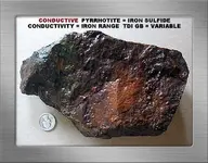
Pyrrhotite is the most widespread, frequently encountered conductive hotrock here in northeastern Ontario’s silver country. It occurs in variably shaped, frequently multi-pound sizes. Although field specimens are weathered to a rusty or deep brown appearance as can be seen below, a fresh surface is a pale brass / bronze color with a metallic luster. Pyrrhotite has a slight, variable magnetism, a feature that easily distinguishes it from commonly occurring tarnished iron pyrite and chalcopyrite. It yields a very distinct sulfurous odor upon impact with a rock hammer.
There is nothing that can be practically done to mitigate its wide, blaring signal other than to recognize and ignore it when found on the surface. Rocks containing sufficient amounts of pyrrhotite cannot be effectively ground-balanced on a VLF unit but these normally discriminate within the iron target ID range. Pyrrhotite is the bane of electronic prospectors here because its abundance can render entire sites unsuitable for detecting with either a VLF or PI unit.
Bench Testing
The ground (phase) balance adjustment can be used to check suspect rocks to determine whether such rocks contain precious metal values, but this technique is subject to a few conditions described below. Let’s use the F75 as our example unit. The procedure can be related to any unit that has the needed sensitivity and sufficient ground balance range to exclude maghemite or other lower GB non-conductive iron minerals from issuing a positive signal.
The F75’s calibrated numerical GB scale can be set to GB45 preferably in the more sensitive non-motion all metal mode. A smaller, more sensitive coil is more effective for testing rocks. Now, bring a suspect rock back and forth to within an inch or two of the coil’s surface. Keep in mind that no response is possible if the electromagnetic field cannot see a potential target inside a rock. Therefore be certain to run this test with the rock rotated in different profiles to the coil. All non-conductive iron mineralized rock signals will go quiet at the GB45 setting regardless of their phase measurement or magnetic susceptibility. This is also a good method to distinguish or identify possible hotrocks in your area.
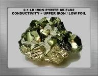
It is possible that such rocks could contain precious metal values that will never be heard because of their disseminated state, or more likely because of the overwhelming negative threshold resulting from the iron minerals in the rock. If there is sufficient metal or conductive sulfide in a given rock to overcome any non-conductive iron mineral response present, these will easily respond at the GB45 setting. If you ensure the non-motion all-metal mode is used with the highest, stable sensitivity possible, even at GB45 this is a remarkably sensitive test with this particular unit. For example, even an extreme low conductor such as iron pyrite in much smaller samples than the specimen below yield a distinct signal at the GB45 setting.
The important point is that non-conductive iron mineralized rocks will not issue a positive signal at the GB45 setting, and therefore can never be confused with positive sulfide or metal responses. One has only to determine the appropriate GB setting on other capable units to duplicate this test method.
Information on the subject of this essay sometimes seems inadequate or even a bit elusive. The foregoing gives you my understanding about these ground-monitoring features and how we can use them for a number of tasks. Hopefully you will find this information practically useful in the field and when evaluating samples.
Jim Hemmingway
February 2011
Last edited:

