✅ SOLVED Belong to a car?

njrelicgairl

Hero Member
Jul 1, 2013
524
1,041
warren county NJ
Detector(s) used
Whites coin master and Vanquish 540
Primary Interest:
Metal Detecting

Attachments

  • 20221109_111608.jpg
    20221109_111608.jpg
    924.7 KB · Views: 101
  • 20221109_111555_HDR.jpg
    20221109_111555_HDR.jpg
    887 KB · Views: 63
Hi njrelicgairl

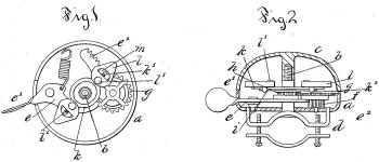
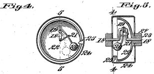
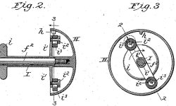
The only likely-looking patents for 23rd February 1897 were for bicycle bells, of which there were three, this presumably being the broken top part of the housing which produces the ringing.

Philip C. Arnold (577,408)
1bell.jpg

Ferdinand Meyrose & William H. Curtis (577,488)
2bell.jpg

George F. Carlie (577,718)
3bell.jpg


I doesn’t look like a part of Meyrose & Curtis’ invention, but I think it could be one of the other two… assuming it’s of an appropriate size (you didn’t give us any indication).

PS: It can’t be 1997 since no US patents were granted on 23rd February that year.

PPS: The first affordable car wasn't available in America until 1908... eleven years after the date for the patent.
 

Last edited:
Upvote 11
Hi njrelicgirl

The only likely-looking patents for 23rd February 1897 were for bicycle bells, of which there were three, this presumably being the broken top part of the housing which produces the ringing.

Philip C. Arnold (577,408)
View attachment 2054577

Ferdinand Meyrose & William H. Curtis (577,488)
View attachment 2054578

George F. Carlie (577,718)
View attachment 2054579


I doesn’t look like a part of Meyrose & Curtis’ invention, but I think it could be one of the other two… assuming it’s of an appropriate size (you didn’t give us any indication).

PS: It can’t be 1997 since no US patents were granted on 23rd February that year.

PPS: The first affordable car wasn't available in America until 1908... eleven years after the date for the patent.
A ringing good post Red-Coat, I agree.
 

Upvote 3
Hi njrelicgairl

The only likely-looking patents for 23rd February 1897 were for bicycle bells, of which there were three, this presumably being the broken top part of the housing which produces the ringing.

Philip C. Arnold (577,408)
View attachment 2054577

Ferdinand Meyrose & William H. Curtis (577,488)
View attachment 2054578

George F. Carlie (577,718)
View attachment 2054579


I doesn’t look like a part of Meyrose & Curtis’ invention, but I think it could be one of the other two… assuming it’s of an appropriate size (you didn’t give us any indication).

PS: It can’t be 1997 since no US patents were granted on 23rd February that year.

PPS: The first affordable car wasn't available in America until 1908... eleven years after the date for the patent.
I can get you a size, I will post it tomorrow.
 

Upvote 0
I believe it is the base of a vintage collapsable cup.
View attachment 2054638

That sure looks like it!


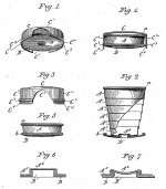
John Lines (577,764):
Collapsible Cup.jpg
To the bottom of the cup I secure a dished disk-shaped foot B, having an inwardly turned bead b. A simple and effective means for securing the cup-like ring A to the said foot is shown in Figs. 6 and 7.

Fig. 6 shows the cup-like ring A as being formed with a central inwardly-projecting boss A and the foot as being formed with a similar central inwardly-projecting boss B1, enough smaller in diameter than the boss A6 to fit within the same. Then after the boss B1 has been entered into the boss A both of them are upset, as shown in Fig. 7, whereby the bosses are broken down outwardly and the foot firmly clamped onto the cap A5 and this without the use of any solder or without breaking or cutting the metal.

The foot B is very slightly larger in diameter than the beaded edge of the ring A and performs the twofold office of forming a support for the cup when extended for use, and also of forming an attachment for the cover or cap C of the cup.
 

Upvote 4
I believe it is the base of a vintage collapsable cup.
View attachment 2054638

That sure looks like it!


John Lines (577,764):
View attachment 2054653
To the bottom of the cup I secure a dished disk-shaped foot B, having an inwardly turned bead b. A simple and effective means for securing the cup-like ring A to the said foot is shown in Figs. 6 and 7.

Fig. 6 shows the cup-like ring A as being formed with a central inwardly-projecting boss A and the foot as being formed with a similar central inwardly-projecting boss B1, enough smaller in diameter than the boss A6 to fit within the same. Then after the boss B1 has been entered into the boss A both of them are upset, as shown in Fig. 7, whereby the bosses are broken down outwardly and the foot firmly clamped onto the cap A5 and this without the use of any solder or without breaking or cutting the metal.

The foot B is very slightly larger in diameter than the beaded edge of the ring A and performs the twofold office of forming a support for the cup when extended for use, and also of forming an attachment for the cover or cap C of the cup.
They put pat dates on these?
 

Upvote 0
They put pat dates on these?

It was pretty much standard practice when you produced something for which you held patent rights (or a licence from the patentee). It served as a warning to those who might be inclined to copy your invention. As a practice, it has fallen out of favour these days... or at least quoting the grant date has.
 

Upvote 1
It was pretty much standard practice when you produced something for which you held patent rights (or a licence from the patentee). It served as a warning to those who might be inclined to copy your invention. As a practice, it has fallen out of favour these days... or at least quoting the grant date has.
Thank you for explaining.
 

Upvote 0

Top Member Reactions

Users who are viewing this thread

Back
Top