I'm doing a test right now...
I came across this post at a good time. I'm actually running a comparison test on a PowerEx NiMH rechargeable 9.6V versus an off-the-shelf Duracell Duralock alkaline.
A couple of things before I go any further...
Not all 9V batteries are exactly the same physical size, the industry has a set of guidelines for sizing and there is a millimeter or so of tolerance on the min and max measurements. Rechargeable 9V batteries, more often then not, are slightly wider, thicker, longer, or a combination of those...it's just the nature of their design. Usually, it's only a millimeter or so, but when your detector has a very tight battery compartment, like my Tesoro µMax, then it makes a difference. I originally was going to test the EBL 840 9V Li-ion, but I couldn't close the battery cover properly, so I returned them, did a little sizing research and tracked down the PowerEx...this particular battery is exactly the same size as off-the-shelf alkalines.
9 volts does not always mean 9 volts. A typical off-the-shelf alkaline battery is made up of 6 individual 1.5V cells arranged in series to give you 9V(about 9.5V fully charged). Rechargeable batteries use 1.2V cells and rechargeable batteries generally come with stacks of six, seven, or eight 1.2V cells. This would make your actual fully charged voltages 7.2V, 8.4V or 9.6V (actually a little higher, but for a brief period of time).
99% of the time you see an advertisement for a 9V rechargeable battery; it will be the 8.4V flavor with seven cells. If a company is selling a 9.6V rechargeable battery, they will definitely state that fact, because it will be more expensive since they have to squeeze in that eighth 1.2V cell to get the 9.6V rating. And for the most part smaller cells mean higher quality cells and higher quality cells mean more expensive cells. Also note that a fully charged 9.6V battery actually has a charge of a little over 11V. But this voltage will quickly drop to a 10V range where it truly begins to operate at a solid voltage level.
Anyway, on to my testing. My background is electronics and control systems...PLCs, RTUs, flow computers, etc. Stuff used for personnel safety systems, gas measurement, oil & gas refining. This allowed me to setup a bench test for testing 9V batteries under different conditions fairly easily. Of course, all of this is done during my lunch breaks.

I just enjoy tinkering with that kind of stuff.
I programmed a small PLC to run a duty cycle to apply and remove a load to the battery. This is done through an external relay attached to one of the PLCs discrete outputs. Right now I have the program set to a one hour duty cycle, in other words the battery is under load for one hour then is unloaded for one hour. This on/off cycle continues all day and night. I am constantly monitoring the batteries current draw and voltage and trending this data (5 second sample rate). The test will automatically stop when the battery voltage drops to 7.5V for a period of ten seconds or more. 7.5V is about as low as I would like to go and a drop in performance will start to become noticeable on some 9V systems below this level. Also, the reason I'm repeatedly starting and stopping the load test is to try and simulate turning the power system on and off as you would probably do during normal short hunts. Good thing about using a program is that I can change this length of time to any value I like to simulate different usage patterns.
As for the battery load I'm using, I was originally going to go with a simple static resistive load. But I decided against that route since it wouldn't be a very accurate test of the batteries performance because if the load resistance remained constant, then the current value would have to drop to compensate for the lowering battery voltage (Ohm's Law). Instead I went with current regulative diode (CRD). This cool little transistor will maintain a constant current load on the battery even as the battery voltage starts to drop. The setup I'm using in this test is 24mA constant current draw. This will remain stable anywhere between 5V and 12V...plenty of range for its use here. If you notice 2 diodes in the picture on the breadboard, that's because I'm using two 12mA CRDs in parallel to get my 24mA, but it serves the same purpose.
This is my little setup...yes I know it's messy, Ha! Left to right is the PLC (AB Micro1100), analog input module, two configurable isolators. One allows me to convert the battery voltage 0-12V range to a 4-20mA signal that my input module prefers. The second isolator converts the 0-50mA battery current range to 4-20mA signal. Next are a few terminal blocks and fuse holders for wiring things up and then a couple of 24V relays, one being used to make and break the actual battery circuit. Finally a power supply on the end. All of this hardware I already have in my office and use for other work-related testing.
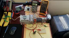
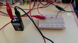
I'm going to explain what's happening in a simple manner. Current flows from the positive terminal of the battery through the two diodes on the breadboard then to the common contact on the relay. When the relay energizes, the relay contact will close allowing the current to continue to the input of one of the isolators where it is calibrated to an analog signal that the PLC can read. In the picture you see the little green light on the relay indicating that it is energized and the battery is loaded. Now the 4-20mA current signal leaves the isolator and is terminated on the analog input module (where the two white wires disappear under the flip cover). There is another red wire coming off the breadboard on the left side that goes to one of the termination blocks. This is the battery voltage reading that then gets conditioned by the other isolator and changes from a voltage reading to a current reading that the PLC is happy with. The two black wires coming off of the analog module are the signal-return or "common" wires that allows the current to return back to the negative terminal of the battery(via the green jumper). And that completes the test circuit.
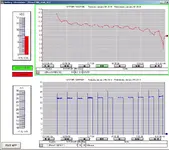
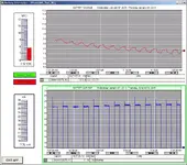
Here is a screenshot of the program I'm using to view what's going on in the PLC program; it's called an HMI interface. It allows me to see the data change in real-time, allows me to trend and print the accumulated data and allows me to stop and start the program at will using the pushbuttons on the screen. The red pen at the top shows the battery voltage values and the blue pen at the bottom shows the current load across the battery. You can see a 24mA load is applied for one hour and then removed for one hour again and again. You can also see how the red pen (battery voltage) has a corresponding dip in voltage when the load is applied and how it recovers when the load is removed.
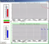
So anyway, there it is. I'm going to run the load test all day and night on the rechargeable battery till it drops to 7.5V and then it will shut off the program automatically. I'll do the same on the alkaline battery and then we will have some useful comparison data. I'll probably update my finding in a few days. I just started the test on the first battery a few hours ago, as you can see from the screenshot, and from the look of it, it will probably last a couple of days before the test stops. Sorry for the long post, but I figured there might be a few people out there who also find this interesting. HH!
PS -
My pictures seem to come out as thumbnails that you have to click on to get the full resolution. If someone wants to enlarge the pictures to full resolution so there is no need to click on them, feel free. Thanks!


 I just enjoy tinkering with that kind of stuff.


